| LIFE OF A GT |
|
|
 | |  | December 31, 2009 - After the big dramatic day of pulling out the engine, I continued to work.
That great engine is worthless without the wiring to run it, so I spent several days pulling out what I needed. Yanking out a wiring harness without chopping it up requires fairly substantial disassembly of the car, including pulling the dash.
GM made some weird choices when it comes to connectors. Some are the excellent GM "Weatherpak" ones. But some of the parts that appear to be sourced from the outside use a wide variety of completely different connector designs. It's a bit ridiculous, making the wiring harness appear to have been designed by a half dozen teams that never actually talked to each other.
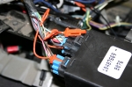
A number of connectors are locked in to place with a secondary pin. In the picture, the orange insert needs to be pulled out (which, in this case, involved a dental pick to depress the small and difficult to access tangs) before the blue section can be removed. Why? It certainly makes the car harder to assemble and to work on. Most of the other connectors have a more common clip that can be released easily. But for some reason, there's a guy at Chevy who's paranoid about how secure a connector has to be.
entry 238 - tags: wiring | | | 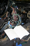 | December 31, 2009 - I'm trying to isolate the wires I need so I don't need to pull the entire harness from the car.
There are probably easier ways to go about this - more on that later - but I figure I'd rather put in the extra effort just in case.
Remember those disparate wire harness engineering teams that wouldn't talk to each other about connector design? They also didn't communicate on wire colors either. There simply aren't enough colors to go around, and the common trick of adding a stripe to distinguish between say, a white wire and a white wire with a green stripe. Adding the stripe increases the number of distinct wires dramatically. Instead, the instrument cluster has two white wires coming out of it. One is for the skip shift system, the other is the speedometer signal. Both go to the Powertrain Control Module or PCM. Thanks Chevy!
Now, the easier method. I just remembered that Painless makes an LS wiring harness. In fact, it turns out they make one for the unique 1998 Camaro PCM. It includes everything you need to run the engine and nothing else - even a fusebox - and is designed for jobs like mine. As a bonus, they'll also reflash your PCM for free, disabling the need to use a key with a particular resistor stuck inside or turning off the need for rear O2 sensors. The total is right around $500. When you consider I've probably taken $500 of potential resale out of the Camaro (should it remain a viable car, anyhow), I'll have to pay for the software to reflash the PCM and I may end up spending some money on a fusebox, it may have actually been a money-saving choice to make. Oh well, I'm committed to this plan now.
entry 239 - tags: wiring | | | February 10, 2010 - I think I've sorted out how the fuel system will work.
I've ordered the always-necessary random bits and pieces. Turns out using AN fittings won't be such a problem, and this way I'll have a sexy braided fuel hose! It should come together fairly quickly when I start work. I've also ordered a muffler to confirm fitment.
I'm procrastinating. I really should be working on the metalwork around the transmission. But Janel's under the weather and asleep on the couch, so it would probably be rude to fire up the grinder, drill and Sawzall. Soon.
What I'm really trying to decide is if I should just bite the bullet and pick up a Painless wiring harness. I've wired cars from scratch before, and it's not that much fun. I've modified stock wiring harnesses, and that's possibly even less fun. It's so tempting to simply have something I can plug in with no mystery or work on my part. If it'll cut a month off the build time - that seems like a lot, but it's actually plausible especially when you consider my lack of experience with these engines - then it's probably worth it. I'm getting so lazy.
entry 281 - tags: wiring, fuel | | | 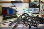 | February 16, 2010 - The folks on the LS1tech.com forum are very enthusiastic about modifying stock harnesses.
So before I dropped a big pile of cash on a Painless setup, I figured I'd give it a shot. I started by making a spreadsheet of all the wires in the ECU connectors, what they did and if they should be kept.
It turns out that even the oddball 1998 Camaro harness is very well documented. With the help of LS2.com this only took a moment. I walked through the list and put an X beside every wire I wanted. No VATS (anti-theft system), no EGR, no second O2 sensors, no fuel tank pressurization and no charcoal canister. Also, I didn't feel it necessary for the low oil signal to pass through the ECU.
All of this work was done with the Jaguar looking on, representing Lucas.
entry 285 - tags: wiring | | | 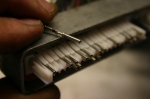 | February 16, 2010 - Nice work, GM!
The connectors for the ECU (actually, I think the term is PCM but I'm going to stick with my usual) might be huge, but after you pop off a couple of plastic covers I discovered that they're ridiculously easy to modify. Simply lift the wire terminal of choice upward a bit and lift the tap on top a bit further, then push. The wire slides right out. I used a dental pick when I was dealing with a single terminal in the middle of a bunch of others, but it's possible to do this with your bare hands.
A couple of minutes later, I had removed the wires I didn't want. If I decide to put them back later, they just push in.
entry 286 - tags: wiring | | | 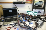 | February 16, 2010 - After all the extra wires were popped out of the connector, I started pulling them out of the harness.
I'd follow them back through the other wires to find what connector they went to. I unwrapped the harness (put together with a minimum of super-sticky tape, unlike the Miata!) and used zipties to hold it in shape.
Some connectors had other wires that were shared, typically power and ground. These were chased back to junctions with other wires and snipped off. The pink power wires will have to be taped up before I energize the harness. Gradually, the harness got simpler and simpler.
I used LT1.com (no, that's not a typo) to identify some of the wires in the various inline connectors. The "keep" wires that passed through these were typically things such as gauge information, so I pulled them out of the inline connectors, coiled them up and labelled them. I also replaced a hacked-up tach wire with one of an identical color - did the Camaro previously have a big aftermarket tach?
The Jaguar approves.
entry 287 - tags: wiring | | | 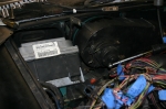 | February 16, 2010 - With the harness simplified, I laid it out over the engine.
Next I had to find a place to stash the enormous ECU. It's huge! Newer ones are smaller - but I don't have a newer one. With the removal of the AC system inside the car, there's some room above the passenger's feet. It would be hard to disguise the big modern heatsinked box though.
The MGB, like many other Little British Cars, is ambidextrous and uses the same chassis for RHD and LHD applications. There are even plates covering over the holes where the pedals would pass through the firewall. This leaves a fairly large space where the RHD pedals aren't, and it's the perfect size for the ECU. As a bonus, the Camaro keeps its ECU in almost exactly the same place so the wiring lengths are almost perfect. I can even reuse the Camaro bracket.
It seems I get lucky with packaging once in a while on this project.
entry 288 - tags: wiring, packaging | | | 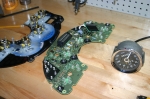 | February 16, 2010 - My plan has been to somehow stuff an electric speedometer inside the classic Smiths case.
The Camaro's T56 uses an electronic sender and the MG has a completely mechanical version.
Of course, I'm a long way from needing a speedo. But I'm not feeling completely healthy and poking around wires is more attractive right now than cutting and welding. Thus the electric emphasis of the last few days.
Well, it's not going to be easy. Looks like quite a challenge, actually. Enough of one that I started looking for alternatives. I already know of one, which is basically a small electronic motor in a box that takes an electronic signal in and spins a cable at the appropriate speed. It's a decent option, although a bit more of a kluge than I'd prefer. If you're converting a Miata with molded plastic gauges, you don't have a lot of other options. But the MG uses individual gauges, of course.
Poking around, I discovered that there actually exists an electronic Smiths speedo. It's not a perfect match to what I have, but it's awfully close. Close enough to work. And as a bonus, it's actually significantly less expensive than the little "gerbil box" motorized adapter. Excellent.
What about the tach? It's expecting a four-cylinder, so it'll read twice as fast with 4 pulses per crank revolution instead of 2. Some poking around pulled up an article on the British V8 site that explains how to add a potentiometer to easily make the tach adjustable. But wait, it gets better. 1972 was the only year to be fitted with a potentiometer from the factory. At the time the article was written, it wasn't known if this gave enough range to make it work with a V8, but I'm very willing to find out. If not, I'll just solder in a different one. Perfect.
entry 289 - tags: gauges, wiring | | | 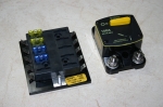 | February 26, 2010 - Parts are starting to arrive from all over!
Del City provided this 10-circuit fuse block. I figure I only need 6, but more can't hurt. The MG only has about 4 and they're all devoted to lighting from what I can tell. If I only need 6 of these 10, I'll integrate the two boxes.
I also picked up a big master circuit breaker. It'll give a bit of "uhoh" protection. It also lets me cut the power to the whole car, which is really handy when it comes time to work on things or to store a car for a while.
Most of the post-header exhaust parts are here as well, and the big box from AFCO will arrive Monday. I'll have no excuses for not working on the car shortly!
entry 297 - tags: wiring, exhaust | | | 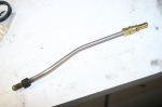 | May 27, 2010 - The first step in the fuel system - at least, from the point of the fuel.
The flare on the fuel tank is some weird British size, so I attached a new fitting to a short piece of the original fuel pipe. The fit on the compression fitting is so tight that I had to stick the pipe in the bead blaster and clean off the surface crust before it would slip over. The cleaner pipe will help it seal as well.
The two missing adapters I need showed up today in ludicrously large boxes, so I have everything I need to finish the fuel lines. I also started working on the wiring, and I've decided where the ECU will go. It'll be fairly straightforward from here.
entry 337 - tags: fuel, wiring | | | 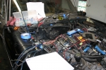 | June 16, 2010 - Wiring time!
This means I'm referencing a handy four-page schematic of the Camaro wiring, the one-page diagram for the MG and referring to the big 100-page book of Miata wiring once in a while. The Camaro wiring is actually going pretty well. The biggest problem is hunting down and fixing a couple of connectors that were damaged either when I pulled the engine or beforehand.
Integrating it into the MG wiring is a bit more challenging, although it did help when I figured out I was trying to reinstall the MG harness the wrong way in the car! I think I need to make a photocopy of the MG diagram and start identifying which sections to keep and which ones will be deleted.
Sharp eyes (and real obsessives) might notice that I've flipped the fuel rail over on the engine. This puts my fuel feed on the passenger's side instead of the driver's. It's just a bit easier to run it that way. Let's hear it for symmetrical intake manifolds!
entry 346 - tags: wiring, fuel | | | 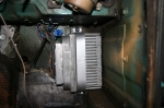 | June 16, 2010 - One of the big roadblocks to the wiring was figuring out how to mount the massive ECU.
As you may remember, I was originally going to put it in the engine bay, but that was a pretty tight fit. I was also trying to reuse the stock bracket, and that was proving to be difficult. There's a bracket from the S10 or some sort of van that is a bit easier to mount in a non-standard location and arrangement, but I finally realized I could simply mount it with a solid strap, as seen here. It's solid and secure, but easy to remove when needed.
The ECU is located at the end of the passenger's footwell, which means the wiring harness can easily drop down through the hole that would have been used for the pedals in a RHD car. Cool. I'll probably put a plate over top of it to hide the ECU and give the passenger a good solid foot rest - but not yet.
entry 347 - tags: ECU, wiring, packaging | | | 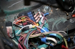 | June 16, 2010 - The GM computer needed a few new circuits.
The MG only has five fuses (that I know of) in the entire car, but I wanted more than that! To be fair, one of the fuses in the new box is a duplicate of the fuel pump fuse in the old one - I'm not sure if I'm going to retain that particular one.
The wire colors here are the GM ones, they're quite fond of pink wires. Thus the labels. The wires will be corraled further when I'm done as well, right now they're just being roughly loomed together.
The new fuse box sits in the engine bar, where the pedal box would be on a RHD car. The square hole at the bottom of the picture is the one that lets the wires run down to the ECU, which is just barely visible in there. I'll adapt the factory cover to make this look good.
entry 348 - tags: wiring | | | June 23, 2010 - Work continues, but not too quickly.
I've been moving slowly - but the main power lines from the trunk-mounted battery to the starter, alternator and main breaker are now all in place. The breaker can be tripped manually so I can kill the power to the car if required.
I'm now trying to figure out how to run the original MG wiring harness up to the front of the car. It'll continue to handle housekeeping chores like brake lights, fuel level and turn signals. The problem is the hot exhaust criss-crossing under the car - I want to keep the wiring clear of it. The main power line runs through the transmission tunnel, but the MG harness is about 4-6" too short to work that way. I'll play with it again tonight and see if I can find a bit of extra length.
entry 351 - tags: wiring | | | 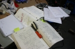 | September 3, 2010 - Time for the wiring to commence.
I have a few Miata parts (ignition switch and the headlight/turn stalks), a whole bunch of GM parts (the whole point of this project, really) and the leftover MG parts (ie, housekeeping). So I'm having to do a lot of cross referencing and some mental redesigning. It's kind of amusing - the MG diagram is one 8.5x11 page. The GM engine diagrams are on four 8.5x11 pages. And the Miata book is about 120 11x17 pages. But it's more useful!
entry 386 - tags: wiring | | | 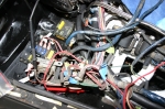 | September 3, 2010 - The ugly truth.
There's a spot in the engine bay above the passenger's feet where one of the main MG harnesses erupts from the fender. Just below that, I've mounted the GM computer and rerouted the other main MG harness through the cockpit to arrive at this same location. It's quite a traffic jam.
I'm tracing through the MG harness to pull out unused wires and to figure out how some of it works. I'm doing a lot of electrical forensic work as I try to identify a number of the connections. I know there's a hookup for the reverse lights in there somewhere...
The first splice between the GM and MG harnesses was made yesterday - the alternator light. The ignition switch is also wired in, so I can check that the appropriate circuits will be energized when the battery is installed. Since the MG harness has a few unknowns for me, I'm being particularly careful to avoid stray electrons.
entry 387 - tags: wiring | | | 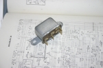 | September 3, 2010 - I do love my bead blaster.
This is a relay for the starter solenoid - probably added to the MG over the course of production to protect the poor ignition switch from the power needed to trigger the solenoid. The Miata switch is robust enough to handle it, but the wiring in the MG harness is a little smaller than I'd prefer. So I'll keep my relay to trigger my solenoid to trigger my starter. At least, that's how I'm thinking now.
Just look at what 20 seconds in the bead blasting cabinet did to this (probably) 38-year-old component. There's no corrosion on those contacts!
entry 388 - tags: wiring, bead blaster | | | September 9, 2010 - Power!
With a few spare minutes in the garage and a freshly connected main relay, I hooked up the battery to the car for the first time. First, of course, I had to come up with a good grounding point. Hopefully I did.
When I connected the battery, nothing happened. That's good.
Then I flipped on the main circuit breaker. Nothing happened. That's good.
Then I turned on the ignition and saw a light come on inside the dash. Must be the alternator light. I also heard the main relay click over and the fuse panel for switched power came alive. That's good!
No sparks, no shorts, no nasty smells. All the smoke stayed inside the wires. This may not seem like a big step, but now that I know I have a smoke-tight electrical system it'll be a lot easier to trace wires and determine that everything is hooked up correctly.
Woohoo!
entry 393 - tags: wiring, smoke, electrical | | | October 5, 2010 - Trying to pick up from where I'd been, a month later, is a challenge.
Especially with wiring. But I've sorted out what I was doing and I'm starting to make forward progress again. Nothing big or exciting, just careful connection and testing of one circuit at a time.
entry 396 - tags: wiring | | | 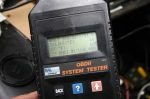 | October 6, 2010 - Woohoo!
This might not look like a whole lot, but it means the electrical system is live and I can talk to the engine computer. All the sensors that could be expected to have readings with the engine off have readings, and they're all accurate. The throttle is wedged slightly open in case you're wondering about that 11.8% reading on the TPS.
Once again, no smoke was released. This is all going well.
entry 397 - tags: wiring | | | October 6, 2010 - So?
Did it start? Well, no. It cranks happily and I did get it to cough really briefly, but overall it's just not exciting. Here's where the OBD-II scanner comes in handy. I can see that all the various sensors are reading properly - there's even measured airflow going through the intake on cranking - but the engine RPM is stuck at 0. If the computer doesn't think the engine is spinning, it's not going to try to fire the injectors or spark the plugs.
I checked the wiring for the cam angle sensor and the crank angle sensor. It's good in both cases. When Janel's home tomorrow, I'll check to make sure I'm getting spark. But that 0 RPM reading kinda tells me what I'm looking for first...
entry 402 - tags: start, wiring | | | October 12, 2010 - More progress.
A quick test with a smoke machine uncovered a vacuum port on the back of the intake manifold, underneath the MAP sensor. Almost impossible to see, and now capped. With that done, the idle quickly settled down under 1000 rpm and was continuing to improve when I shut things down. So it's looking as if the engine is a happy bunny.
I found an error in the wiring diagram I'm using. The engine computer is supposed to have a constant 12v feed to store all the various internal settings. According to the diagram, that feed was switched power so it only turned on with the key. Every time the computer loses power, it needs to relearn various settings such as the idle - so this would have been an annoying problem. Fixed now!
I'm working on related wiring now. The coolant gauge is hooked up, but the engine hasn't been hot enough to test it yet. I'm working on the tach now.
I also picked up all the pieces I need to complete the braking system. At least, I think I have all the pieces now. I'll start working on that soon, as it's the biggest step preventing me from actually driving the car. Ooooo!
entry 406 - tags: brakes, wiring, engine | | | October 13, 2010 - I'm all excited about working on the car right now.
But I'm very easily side-tracked. For example, I need to build the brake system. I had my head in the front wheel wells trying to figure out the best way to route the lines - it's hard to keep them away from the header - when I spotted the wiring for the front lights dangling. They'd been damaged at some point in the past and repaired poorly with solder. Well, it would be easier to patch them before I assemble the suspension, so I quickly hooked them back up with good connections. Then, of course, I wanted to see if they'd work and that led me to the steering column combo switch, which came from a Miata. So I ended up poring over Miata wiring diagrams and MG diagrams and trying to figure out how they each work so I can splice them together.
At the end of the night, I had functioning headlights but I hadn't energized the turn indicator circuits yet, and I'd temporarily run a switch in place of the headlight relay as I puzzled out the logic of both systems. Naturally, I'd made no progress on the brakes.
But it was fun, and I've turned the MG into a giant V8-powered flashlight.
entry 407 - tags: wiring, lights | | | 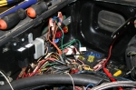 | October 19, 2010 - The wiring is moving right along.
It may not look any better than it did before, but the majority of the MG circuits are hooked up now, and the back half of the car is almost fully functional. Reverse lights, taillights, brake lights - all I need to do is make the flashers work, and that's just a matter of figuring out where in the harness the flasher unit was plugged in before! The main front/rear wiring harness has been relocated to run inside the car as there are hot exhaust pipes running back and forth underneath now, and the length is pretty much perfect. The wiring is really proving to be an easier job than it should be, in large part because the lengths of both the MG and GM harnesses have been bang on.
entry 408 - tags: wiring | | | 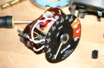 | October 31, 2010 - I've been learning about MG tachometers.
It's fairly normal to have trouble with older tachometers and LS conversions due to the signal from the GM computer. The usual problem is a voltage one, and the solution is a pull-up resistor. That didn't work.
So I asked the folks on the Grassroots Motorsports forum, and it turns out it's the tach used in the MG. Up until sometime in 1972, they used an inductive loop inside the tach to measure the ignition pulses - that's it with the white wire and the copper winding. Well, this works well with points but not with newer ignitions, it would seem. And of course, our 1972 MG has the old style, identifiable by an RVI part number on the face.
One piece of information I found suggested that dropping the number of loops of the white wire would help, but that didn't work. I suspect that's for when you change from points to an electronic ignition, and the distributorless setup from the GM computer is just too different. I guess this problem is well known in MG circles.
Luckily, there's no shortage of MGBs that have been turned into parts cars. There's an "RVC" tach on eBay right now with an identical face design, and it'll play nicely with the GM computer. I may still need the pull-up resistor, but we'll see when it gets here.
An interesting little side trip into gauge electronics, I have to say. And one that can be sorted out fairly inexpensively.
entry 418 - tags: tach, instruments, wiring | | | 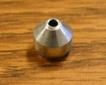 | November 10, 2010 - One step forward, one step back.
Good news - the new tach works! Well, it works once you remember to actually connect the GM tach wire to the MG harness. Interestingly, it seems to read accurately. I didn't have an OBD-II scanner plugged in to read the exact engine speed to confirm, but the car seemed to be idling right around 1000 rpm cold and that's reasonable. I checked the idle at right around 900 after the drive the other day. Interesting - I'd heard the LS engines put out a "four-cylinder" signal, but I figured that was just because a lot of new fours use a waste-spark ignition and thus look more like an 8. Regardless, I'm not going to complain about it! That was easy.
I also spent some time on the brakes. A bit of fooling around and I managed to get rid of a big air bubble in the front of the master cylinder. Voila, a hard pedal! Nice and hard. But the front fitting on the master was still leaking. This will not do. So I pulled it off and yup, the flare looks deformed.
I figured this was probably the case on Sunday when I was bleeding the brakes, but I was hoping that tightening the joint would solve the problem. Of course it didn't, and in doing this I also damaged the seat in the master cylinder - that's it in the picture. No surprise here. Luckily, the seats can be removed so I'll just call Wilwood and order a replacement.
At the same time, I noticed that the master had a big F and R on the outlets. Now, from my understanding, there shouldn't be any difference between them. I did read a blurb in Hot Rod or Car Craft a while back claiming there was and that swapping the F and R lines around solved a soft pedal problem. I still don't understand how - but since I had to rebuild one of the lines to fix that flare anyhow, I figured I'd swap them. This means new lines for both the front and rear outlet, both pretty short but relatively complex. So now I'm back to no brakes at all. Still, I have a clear vision of the way ahead.
entry 437 - tags: brakes, tach, wiring | | | 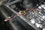 | November 11, 2010 - While poking around the engine bay, I decided to trace this joint connector back.
It was originally up at the front of the engine after running up along one of the fuel injector legs of the harness. Weird, there's no reason for it to do that. I'll shorten things up.
entry 442 - tags: wiring | | | 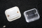 | November 11, 2010 - Sometimes you just have to do little stuff that feels good.
The reverse light lenses on the back of the car looked awful. Back when the MG was still on the road (two years ago!) I ordered a new set. I put them on today and wow, they look good! Two minutes worth of work and I get a feeling of satisfaction.
Of course, this also meant I needed to make sure they were working. Naturally they were not. After a bit of digging around, I found that I'd misidentified the feed wire from the front of the car. I swapped that around, plugged in the lights and one worked! The other, not so much. The cracked lens had let in dirt and moisture, so it was all crusty inside and the contacts were corroded. I stuck it in the bead blaster, gave it a quick shot and it looks brand new! I never thought I'd use the blaster to rejuvenate electrical parts, but it really works nicely on bad contacts. And voila, bright lights in the rear.
Of course, while I was working on electrical stuff I decided to find out why the turn indicators weren't working. After a bit of digging around, I found out that the turn indicator wiring passes through the hazard light switch. Okay. I plugged that in and got...inconsistency. The flasher worked sometimes, but usually not. I checked voltages and found out there was a lot of resistance inside the switch. Basically, the contacts were all corroded. So I disassembled it, stuck it in the blaster and put it back together. Pretty interesting to do, actually. Now I know just how a Lucas hazard light switch works!
That got rid of my resistance, but the flashers are still have a bit of character. There's just enough unevenness in the tempo of the flashes to make you realize it's a mechanical relay working off heat instead of an electronic one!
Looking at the Moss catalog, it appears that hazard switch I fixed is a 1972-only part. It changed in 1973.
entry 443 - tags: wiring, reverse lights, electrical, turn indicators | | | 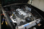 | November 15, 2010 - Here's the current state of the engine bay.
Still some way to go on wiring, but I'm waiting until all the wires are run before covering them up. I'm not sure how to handle the big junction by the fuse boxes, between the MG bullet connectors and the sheer number of wires it's a pretty big bundle. I'm tempted to just build a box to sit over top of it all and hide it from view! Until the car is fully debugged, I'll probably just leave it exposed and ugly.
Currently, I'm in the middle of setting up some relays for the future cooling fans. And in case you're wondering, the note on the rad says "Hook up heater controls" - a reminder to do it when the rad comes out.
entry 454 - tags: engine bay, wiring | | | 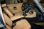 | November 24, 2010 - The interior looks pretty good!
Janel points out that maybe it needs a dashboard, but I'm looking at what's actually there. The center console is just sitting in place, and it will have to be modified at the rear to deal with that brace. Still, it suddenly looks like a real car. Almost...
The front bumper, front valence and grille are all installed as well. Am I dressing up the car to make it look good? Why, yes I am! Family is coming over for Thansgiving dinner tomorrow and I want to make it look good. But I'm not rushing any of this, it was actually time to install the interior. This will also make it easier to drive for shakedown purposes. The dashboard will stay out for a while so I can easily continue wiring.
entry 471 - tags: interior, wiring, assembly | | | December 1, 2010 - Alignment time!
I took the car down to the local alignment shop where they know me pretty well. It's the sort of place where they're not really surprised when I show up with a V8 MGB. The car was a big hit, though. The guys there are the sort who can see past thinks like chopped up fenders and exposed wiring to see the coolness underneath.
So how did it fare? Well, we discovered that if I want less than 1.5 degrees of negative camber on the right front, the shock will hit the control arm. That can be fixed with a bit of grinding on the arm or a relocated bracket, so it's not a big deal. Besides, 1.5 degrees might be about right. When the car drove in, it had -3 degrees on one wheel! The only other problem report was that the Panhard bar is set to the minimum length and it needs to be very slightly shorter to center the axle. Right now, it's 0.27 degrees off. Interesting measurement, that, it's the angle from the center of the rear axle to the centerpoint of the two front wheels. Odd.
The final result is -1.5 degrees of camber, 5 degrees of caster and 0.04" of toe-in. I might remove the latter but that's easy to do at home. The rear, of course, is a solid axle so the alignment numbers are pretty boring. It had 0.27 degrees of thrust angle from my eyeball setup, not bad at all.
One nice thing to see what that my wheelbase is within 0.1" side to side. Looks like I managed to get those control arm brackets in the right place!
And of course, then there was a Lucas moment. The car refused to start. A bit of troubleshooting revealed that the PCM wasn't getting power but other switched circuits were. That's a fairly straightforward problem, as it's very simple wiring. A bit of poking and wiggling and I woke it up again. I suspect it was a bad crimp in one of the spade connectors, so when I got home I cut it off and installed another. This particular wire had been an early installation, and it's been yanked and pulled multiple times at a sharp angle over the course of the build. No harm done, that's the sort of thing you expect on a shakedown like this.
So, how does it feel? Well, I was mostly thinking "I'd better get home before that connection give me more trouble", but it does feel better. The steering still doesn't self-center very hard, so I'm going to check for friction in the column. But it does feel more planted. I'll get it on the highway tomorrow for some higher speeds to see.
entry 490 - tags: alignment, wiring | | | 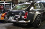 | December 5, 2010 - The rear end with the new lights.
Sharp eyes will also notice that I "shaved" the side markers as well (okay, I removed them and stuck a piece of black duct tape over the holes) and swapped the overriders for the older design. The 1972 ones have a rubber insert. Here's the "before" picture.
I'm really happy with the result. Janel described the older lights are more streamlined, and I think she's right on. They look much better. With all the changes, the car just looks cleaner from the rear. I actually had a set of new lenses for the previous taillights, but this is much nicer.
Of course, this light work wasn't without a certain amount of troubleshooting. The taillights weren't very well grounded, so I added a ground strap to make sure they worked consistently and well. A couple of dodgy bullet connectors also caused me to spend some time cleaning things up. I'll keep an eye on the behavior of those rear lights.
Sometimes it's nice to do the little things that make a satisfying difference. These sort of changes will make the whole car just work better, even if most people can't identify what was done.
entry 502 - tags: lights, wiring | | | 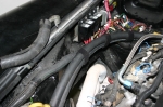 | December 22, 2010 - The cleanup also spread under the hood.
I'm starting to corral the wiring somewhat and bundling it into small harnesses, but I'm going to leave everything accessible until I've done a bit more debugging. Still, it looks better.
The two big hoses in this photo are for the heater. I've strapped them together with velcro strips. It looks pretty good and can be quickly removed and replaced. I'm also using the same stuff under the dash to hold wiring harnesses in place. You can buy rolls of it at Harbor Freight.
entry 520 - tags: wiring | | | December 26, 2010 - I decided it would be a quick and easy thing to check the fans out by just grounding one of the wires on the relay.
I tried it...and nothing. A bit of probing with the test light revealed there was no power at the relays - and a check at the fusebox showed two blown 20A fuses, one for each fan.
Looking at the fan ratings, they're supposed to pull around 13-13.5A. But that's continuous running. I don't have the specs for a startup draw on these particular fans, but one other Spal I've used in the past has a continuous draw of 12.5A and a startup draw of 18A. So it's quite possible that my fuses simply weren't up to the task. The wiring could certainly take it, so I'll just drop in a couple of 25 or 30A fuses and see what happens.
entry 524 - tags: fans, wiring | | | 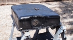 | June 3, 2012 - Hang on a second, the tank is supposed to be in the car.
The car was running just fine...until I had it backed out of the garage and it died. No fuel pressure. I jacked the car up there and started running diagnostics. Of course, the first thing you suspect is the thing you just did. But because it was such a pain to weld the tank back together, I started looking elsewhere.
And I found something. It appeared that the regulator had died on me. When I disconnected it, I got a good gush of fuel out of the pump. Huh. The regulator is built in to a stock Corvette fuel filter that should be good for extended use - but maybe something from the tank plugged it. So I swapped in a new one. Nope. The pump struggled to get up to 40 psi (slowly) when it should have popped up to 60.
So I plugged a new hose on to the pump inlet and dropped the other end into a bowl of fuel. Voila, instant 60 psi. I'd tried this earlier without success, but I think I had the bowl too low so the pump couldn't suck it up. So out the tank had to come.
When I cut the top off, I didn't see anything obvious. But plugging the end of the pickup and blowing in the other end revealed the problem. A small pinhole in the new line where it had been tackwelded to the interior baffle. Not much, but once the pump was pulling hard it let in air instead of fuel. A half second zap with the welder and the pickup line was nicely airtight. Argh.
Welded it all back up again, smeared liquid metal around the seam again (to cover any pinholes in the welds) and the tank went back in. I tested it with a couple of gallons in the tank and again, 60 psi. Excellent.
Then the car refused to start. It cranked and backfired, then went "clunk" and wouldn't crank anymore. I'd been working the battery pretty hard during testing, so I threw on the charger. Just to check, I stuck a test light on a hot terminal in the engine bay. Nothing. Hmm.
I checked across the battery terminals, no problem. I checked from the grounding point to the terminals, no problem. But then I checked from the bumper to the battery. Nothing. Closer inspection showed that the main grounding point (a bolt running through the sheetmetal) was a bit loose. I tightened that up and all of a sudden I had power through the car.
If you remember back, the car's had the habit of not always starting on the first attempt. It would backfire and pop, and then would fire happily if I just cycled the key. It also had a habit of occasionally stopping at the side of the road. I'm thinking the loose ground strap may have been the culprit for the first, although we'll see if that behavior continues. The latter might have been related to that heavily restricted return line inside the tank. That's certainly not a problem before. We'll see what happens now. At the moment, the car is on "close to home" probation.
entry 642 - tags: fuel, troubleshooting, wiring | | |
|

 THE DIARY