| LIFE OF A GT |
|
|
 | | 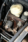 | April 15, 2008 - There's a shield that usually covers the brake master cylinder pushrod.
One of the screws that holds it in place had been damaged by a previous owner, but after a bit of work I got it free. And here's what greeted me underneath. Yuk.
So it's a good thing I ordered a master cylinder rebuild kit yesterday. Moss says the master can't really be rebuilt, but I'm willing to give it a try. It's the difference between a $270 part and a $18 kit.
On a similar note, I got a call today from Gordon Strickland of the B Hive, confirming some of the slightly odd quantities in my order. He was very helpful, discussing some slight differences in the badges that might cause difficulties in my planned grille design.
entry 21 - tags: brakes | | | 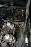 | April 23, 2008 - Time to stop messing around with badges and grilles and time to fix a real problem.
The brakes. The master cylinder leaks badly and has to be rebuilt. I picked up a rebuild kit from The B Hive.
The first step is to remove the master. It's a bit of a puzzle really. It will come out, but you have to discover just the perfect way to twist it. I went a little further in disassembly than I really had to, but I got it out!
entry 38 - tags: brakes | | | 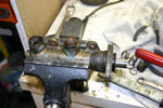 | April 25, 2008 - The master is out of the car and on the bench.
Time to rebuild it!
entry 40 - tags: brakes | | | 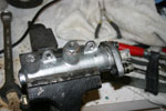 | April 25, 2008 - The first thing I did with the master was stick it in the bead blaster.
I haven't actually done anything to repair it yet, but it looks almost new now!
One thing I did do was install some Time Serts into the mounting flange. The factory used nuts and bolts here, and the lower nut is almost impossible to access. The Time Serts - similar to Helicoils - will let me use bolts that thread right into the master cylinder. Much easier. These particular inserts are too long to be ideal, but they'll work. Tapping the holes in the flange would probably also have been just as effective.
entry 41 - tags: brakes | | | 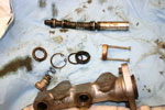 | April 25, 2008 - The master is mostly disassembled.
There are two snap rings that could be easier to reach! A pair of small needle-nose pliers did the trick, though. There's also a nylon spacer that is very reluctant to come out, so I borrowed a trick from the MG Experience forum and inserted a couple of screws to yank it out. A replacement came with the rebuild kit.
The next step was to take the piston apart to replace a couple of the seals. This was the most difficult part of the job. The assembly is held together by a couple of tiny roll pins, and it's difficult to gain access to them without marring the steel. It took a lot of effort (and some frustration) but I eventually won. I used a modified "precision screwdriver" as a punch and ground it down to the perfect diameter after some trial and error.
entry 42 - tags: brakes | | | 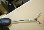 | April 25, 2008 - The inner bore of the master looked very good, much to my relief.
So I gave it a quick hone with this honing tool then put everything back together.
Of course, on reassembly, I had to remove the master a couple of times before I was done. Every time it had to come out, it fought me more. More frustration and I never did clean out the pedal box area as well as I should. I'll get the pressure washer in there soon and give it a good blasting.
entry 43 - tags: brakes | | |  | April 25, 2008 - More painting!
This time, the rear brake drums. They were ugly and rusty and very obvious behind the new wheels. So a shot of satin Rustoleum and we're good. You might notice that this is three different types of black paint so far. I used four, but I forget what the other was for! Oh right, the cover for the pedals.
So, how did the brakes turn out? Well, it took a bit of cleverness to get them bled properly with the dry master, but once we got a bit of fluid moving through they pumped up nicely. So it looks as if my brake master was a success, at least in the short term.
entry 46 - tags: paint, brakes | | | 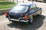 | April 27, 2008 - Time for that all-important first drive!
This is always a big moment in resurrecting an old car. With Basil, it was a late-night run around the block at night with no brakes. Hopefully this one will be a little less exciting.
First off, the car's a bit of a slow starter when cold. I just haven't learned the magic ritual yet. Still, it does eventually roar into life. Yes, roar. There are more holes in the exhaust!
The clutch feels good and the gearchange is really nice. The steering feels good underway, although there's a bit of internal friction. It's as if someone overtightened it to get rid of some play. I'll check that out. The stiff (solid might be a better term) rear suspension certainly affects the experience though. I never knew there were so many bumps on my street!
The brakes have a solid pedal, but need a very strong push. There's probably a bit of rust on the pads, and I think it was getting better. Still, we were mostly cruising along and didn't spend much time on the brakes. I'll bed them in and see if that helps.
The engine seems healthy but the carbs probably need tuning, as the idle never drops down below about 1100. There's also a flat spot on rapid tip-in. Not a big deal, just a bit of fettling required. Oil pressure is strong and all of the gauges work with the exception of the engine temperature.
So, all good then? Well, not quite. The car's spitting out radiator fluid. And it looks foamy. Uhoh. The oil looked fine when I drained it, but either the stock radiator cap is completely trashed (possible) or something's pressurizing the cooling system. I haven't investigated this fully yet. It could be a head gasket, although there's no smoke. Further checking will tell the tale.
On top of that, there are also the usual oddities. The turn signal/high beam stalk is stuck on high beam. There are some weird lights stuck on and others that don't work, so I have to disconnect the battery whenever it's not running. But that's okay, that's part of the fun.
In other words, it's a basically decent little car. It has a list of things that need to be sorted out, but it's all doable and at a good level of difficulty.
entry 53 - tags: driving, brakes, suspension | | | December 15, 2008 - Not much actual work on the car, but lots of planning.
I'm going to go with a three-link rear after talking with a number of road racers and other folks on the Grassroots Motorsports forum. The lateral motion of a long Panhard bar isn't a big deal at all it seems, and it's free of bind and easy to fabricate. So there's that settled. I just have to do it!
I'm also starting to plan the brake system. Very little of it will be MG by the time I'm done. In fact, it's possible it will all be custom. I'll have to wait until the motor position is determined before I can finalize this but it's fun to build it in my mind. Brakes are important to me, and I like putting together good systems.
This is actually a very entertaining part of the build. I have all of the major components so I can start legitimately planning and figuring out how to do things. On top of that is the anticipation of the first big steps coming up - I'm looking forward to that first chop of the frame rail with anticipation and a little frisson of nerves. This is the stage where the whole car comes together in concept, making it a complete machine instead of just a collection of bits that are a reaction to unforseen problems.
I love this part.
entry 108 - tags: suspension, brakes, rear axle | | | 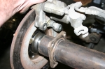 | June 28, 2009 - The new axles have arrived.
Now I can mount the Miata brake rotors and wheels to the S10 rear housing and that opens up a lot of potential work. The picture shows what needs to be done to fit the brakes to the housing - I'll weld a new bracket on to the tube. I'm not sure if I'll try to cut the original one off or not, it'll be a huge amount of work if I do. Depends on the access I have for welding the new one.
I have one wheel mounted on the rear now, I'll install another one soon and roll the whole thing under the car to see how they sit. I already have a pretty good idea, but of course I'm still eager to see it.
entry 190 - tags: rear axle, brakes | | | 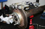 | November 17, 2009 - So, while I wait for suspension parts to arrive, time to look at the brakes.
I'll be mounting a set of Miata rear calipers and discs. I hadn't really thought too carefully about how to do this before, but I could have started as soon as the new axles arrived. As it turns out, it's going to be fairly straightforward.
entry 210 - tags: brakes | | | 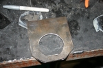 | November 17, 2009 - The beginnings of a rear brake bracket.
Most of my axle uses 2.625" tubing, and it's impossible to find a 2.625" hole saw. This meant lots of grinding for my trailing arm brackets. Are they trailing arms or radius rods? I'm not really sure. Anyhow...
A look at the end of the axle tube revealed that there's a step in the tube size, dropping down to 2.5". That size hole saw I have! And with the axle removed, I can slide my bracket right over the end of the axle tube so I can get a full 360 degree weld. Excellent. The bracket is made of 0.25" steel, nice and beefy. The two mounting points for the caliper are in the same plane, so all I need to do is drill two holes in the right place and weld this on.
Well, almost. Naturally, the bracket uses 10mm metric bolts. I have a 0.375" drill, but 10mm is 0.394". I'd rather not go oversize (7/16 is 0.438") so I'll have to see what my options are for opening up the hole slightly.
The bracket also ends up very close to the end of the tube, so I'm going to put a 0.25" spacer to move it inboard a bit and get more room for welding. That'll also give the mounting bolts for the caliper a bit more meat around them to help them resist shear.
It's kind of funny - I've taken the Seven to two magazine tests over the years. One was in the company of a bunch of other Locosts, the other was to compare against a $75,000 supercharged Atom. In both cases, I was called "a ringer" because of my purported access to equipment and tools not available to mere mortals. Want to know what I've been using for all of my recent fabrication? The holy trinity of a good drill, a sawzall and an angle grinder. Yes, a MIG welder, stick welder and a torch have also recently come in to play, but they're not exactly unusual tools for fabricators. I don't even have a bandsaw. The car is on jackstands in my garage, a far cry from the bead-blasted perfect shell on a rotisserie that some people might expect.
My point here is not to say "oh, poor me", but to point out that you really don't need a lot of equipment to do this kind of work. This bracket isn't as pretty as it might be, but a bit more time with the grinder will fix that.
entry 211 - tags: brakes | | | 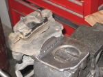 | November 19, 2009 - The brake brackets are ready to weld on to the axle tube.
I'd been trying to figure out the best way to ensure the holes were in juuust the right place. I needed to get the radial location of the caliper just right. Measuring wasn't going to work well as I was dealing with curved surfaces everywhere. After a bit of cogitating, I came up with a cunning plan. Naturally, I wasn't bright enough to take pictures of the process, so I'll have to try to explain.
First, I used a transfer punch to mark the center of the two holes in a piece of 1"x0.25" strap. This is my 0.25" spacer. I drilled those out (I found a step drill that was close enough to 10mm to solve my previous problems) and checked that they were accurate on the caliper.
I then took a couple of bolts and cut them down into short studs, which protruded out of the caliper by 0.25". This way I could hang the spacer on them and butt it up flush against the face of the large bracket piece.
Now the axle and brake rotor were mounted to the rear end. I placed the caliper in the perfect location and held it in place by tightening down the adjuster screw Mazda thoughtfully provided, clamping the caliper in the right spot. Now it was a matter of assembling all of my pieces - the bracket on the axle (loose) and the spacer hung on the caliper. I lined everything up and tack-welded the spacer to the bracket. Now, I had my holes lined up! I drilled the rest of the bracket to match, welded it up and voila.
The second was easier. Now that I had one accurate bracket, I used the transfer punch (wonderful things, these are) to put the holes in the same place and stuck it all together.
Now all I have to do is figure out just how I want to clock the calipers on the axle. I'll mount the rear end to the car and find out if there are any potential interference points with the body.
entry 212 - tags: brakes, rear axle | | | 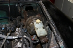 | January 22, 2010 - It's time to make sure I have room for some real brakes.
The car originally came with unboosted brakes, and long-time readers will remember that I rebuilt the master cylinder. That was back when I thought I'd be driving the car as a four-cylinder for a while. Ah, those were the days.
Purists, of course, claim the unassisted brakes are superior in almost every way. But those who are sensitive to subtle hints may have noticed that I'm not much of a purist. I have several cars with unassisted brakes (interestingly, they're all British or replicas thereof) but this car will have a fairly intense power/weight ratio, and I want power assist. Besides, the whole braking system has been replaced with Miata parts, and my rear discs take more pressure to operate than the previous drums.
The problem is twofold - first, there's not much room for a booster underhood. And secondly, the original pedals put the masters above the driver's feet - so there's simply no room for a booster at all in that setup. There are such things as remote boosters which are intriguing. A number of newer vans (and other packaging-challenged cars) also use a "hydroboost", which steals hydraulic pressure from the power steering pump for assist.
But there's an easier way. In 1974 or 75, MG added power assist to the MGB. And in order to do so, they used a very small brake booster, a master cylinder with an angled top to clear the hood, and a different pedal box that put the brake hydraulics in front of the pedal. And it's a simple bolt-in to the earlier cars - although most MG owners go the other way, installing the unassisted setup. I found a complete pedal box, booster and master on the MG Experience website and had it in my hands a week later.
The first trial installation showed that it's a perfect fit. The front outlet is fairly close to my shock tower mount, but a well-placed divot would take care of that. The rubber line that runs close to the booster is actually the vacuum line on the engine. It's just sitting there, I can easily route it with lots of room.
I need to do a bit of figuring with pedal ratios (looks like it's in the 4:1 range) and master cylinder sizes (0.75", apparently) and see what that does for my brake pedal travel. I may want a larger master, as the Miata has a similar (4.1:1) pedal ratio but runs a .875" master. I'll measure the MG one more carefully tomorrow. Luckily, mounting a Wilwood unit is fairly straightforward. So there may be no reason to put that dent in the sheetmetal anyhow.
First, I'll stick this setup in the bead blaster and make it all pretty!
I've been puzzling on the best way to package this for a while, looking at various booster combinations. But I'm really happy with this result. I think it's going to be very clean.
entry 258 - tags: brakes, hydraulics | | | 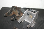 | January 24, 2010 - I love my bead blaster.
That's the pedal box for the boosted brakes on the right, with the unassisted setup on the right.
entry 259 - tags: brakes | | | 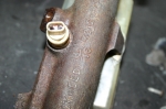 | January 24, 2010 - After a fair bit of calculation, I'm starting to figure out my brake options.
From my measurements, it looks like the MG brake pedal has a ratio of 4.48. That means that 100 lbs of pressure on the pedal is transformed into 448 lbs on the master cylinder. It also means that it takes 4.48" of pedal movement to move the master cylinder pushrod by 1". Basically, it's the same as a gear ratio. The Miata pedal has a ratio of 4.1 according to the manual.
I know the Miata setup pretty well, and the Targa Miata uses the hydraulics from a later Miata setup. The standard Miata master cylinder is a 7/8" unit, and the Sport master is 15/16".
As you can see from the picture, the stock MG master cylinder is 13/16".
So, based on pedal ratios and master cylinder sizes, I compared how much force on the pedal is needed to get 250 psi of line pressure. Why 500 psi? No reason, it's just a constant so I can get an idea of how the different setups would compare in feel for the same amount of braking. I also figured out how far the pedal would have to move in order to push 1 cubic inch of brake fluid, as the leverage ratios and hydraulic multiplication always trade off travel for effort. Here's what popped out of my spreadsheet:
- MG pedal, MG master: 57.87 lbs, 4.32"
- Miata standard setup: 73.3 lbs, 3.41"
- Miata Sport setup: 84.2 lbs, 2.97"
- MG pedal, 1" Wilwood master: 87.7 lbs, 2.85"
So no surprise here, the further you move the pedal the less you have to push on it. Simple leverage. And if you're doing these calculations at home, remember that it's a dual circuit system so you'll get half the pressure and twice the fluid flow as you would with a single circuit of the same size.
According to my calculations, a 15/16" master on the MG pedal (77 lbs, 3.25")would be pretty much right between the two Miata types. But the dual circuit remote reservoir master cylinder available from Wilwood is a pretty unusual piece, and only available in a 1" bore. I need the remote reservoirs to clear the hood, I believe. I do have a few other single circuit master cylinders I can use for test fitting for clearance.
Still, since Janel and I both prefer a nice firm pedal, I'll probably go with the Wilwood 1" setup.
But of course, there's a catch. The booster. All the calculations above give the numbers for an unassisted brake setup. The booster will multiply the force on the pedal to give more force at the master. If the booster has a 2:1 boost ratio, that means it would only take a bit less than 44 lbs of force on the pedal to generate my 500 psi of line pressure, instead of 87.7. And here's the problem. I don't know what the boost ratio of the MG booster is. The Miata one should be around 4.6 according to the manual.
So the end result is going to come down to trial and error, with a bias towards a too-firm pedal instead of a too-soft one.
This stuff is fun. I get to learn all sorts of things.
entry 260 - tags: brakes | | | 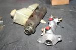 | January 24, 2010 - Sometimes, you have to walk away from a problem for a while.
I don't know why I didn't think of this - the Miata comes with either a 7/8" or a 15/16" master, depending on the application. It has a plastic reservoir that can be removed and turned into a remote setup. And while the bolt pattern isn't correct for the MG, its close enough that I think I could make it work.
I'm also going to make sure the Miata booster won't fit on the MG pedals. If it does, then life is very simple. I'll have a complete Miata brake system with a slightly different pedal ratio. I'll find out tomorrow.
entry 261 - tags: brakes | | | 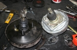 | January 26, 2010 - So, while trying to figure out a few things about the MG booster, it was suggested to me that I try to fit the Miata booster.
As with everything else in this car, make it more like a Miata! Well, my initial reaction was concern that it would fit - the MG part is silver and the Miata one is black in the picture. There's nearly 2" of diameter difference involved.
But I had to try.
entry 266 - tags: brakes, packaging | | | 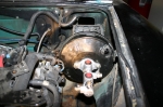 | January 26, 2010 - And voila!
Some light massaging of the inner fender with a 2 lb sledge (about the only part of the inner fender I haven't actually cut off by this point), a new bolt pattern on the pedal box and some clever twisting and turning of the assembly to get it into place, and there's my Miata brake booster installed in the MG.
In researching this, I found that there are actually three brake boosters that have been used over the years, with three different boost ratios. I'll be able to fine-tune my braking effort nicely. Now I just need to source a 15/16" master cylinder from a 2001-05 Miata. Easy enough.
There's just one problem with the fitment of the new booster.
entry 267 - tags: brakes | | | 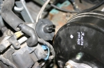 | January 26, 2010 - The booster and the engine end up very close to each other.
Very close. That little port on the head is only about 1/4" from the edge of the booster. It's normally connected to vacuum line that runs from one head to the other, I suppose to prevent pressure buildup on one side.
I looked at a later LS1 and an LS3 in the shop, and I got bitten by the 1998 donor again. In 1999, the heads and valve covers were changed to a center bolt design instead of the peripheral bolt setup I have. This means I can't use a particular Edelbrock coil cover I thought would look great, but that's not important right now. On my engine, both valve covers are the same casting. The little port on the driver's side that's causing me problems is where the oil filler is placed on the other head. On later engines, the driver's side valve cover has a much stumpier protrusion for this port which would give me lots of clearance. This is not a big problem, I'll just whack it off and weld it up. If I decide to keep the connection from head-to-head, I have a few options. So it's not a show-stopper, it's just a bit more work. And it means I'll have to pull that valve cover off - easy to do, just something I was hoping to avoid.
Still, the final result is good. Other than a slightly different pedal ratio, I'm basically running a full Miata brake system. And I know Miata brake systems!
entry 268 - tags: brakes, packaging | | | 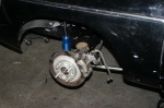 | August 29, 2010 - As promised (threatened?
), the rear axle has been installed. It's full of fluid, has the axles installed, brakes bolted up - it's all looking quite serious now! I still have a few things to do back here, such as working out how to make the Miata and the MG emergency brake systems and locate the platform for the bumpstop. You can see it here sitting on top of the axle. The bumpstop is installed on the chassis. I have to set things up so the bumpstop reaches full compression right before the shock bottoms out. Thus the lack of a spring, so I can do range of motion testing.
I pulled one of the bumpstops off a while back to play with it, and haven't been able to get it back on since. They fit over a mushroom shaped stud, so they have to deform to pop into place. Well, I finally got a brainstorm - I sprayed a bit of Simple Green on the bumpstop (great for lubricating exhaust hangers as well), held it in place, then used a jack to push the axle up. The axle pressed the stop into place with an easy little pop. Sometimes the thinking is much harder than the doing!
entry 371 - tags: bumpstop, rear axle, brakes | | | 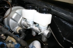 | September 7, 2010 - The new brake master cylinder is here.
I did some calculations a while back on brake master sizes, and the ideal (to match the Miata) ended up being 15/16". My plan to use the Miata booster fell through due to a critical lack of space. Well, I have the choice of the old 7/8" setup from the MG or a 1" Wilwood caliper. Since almost everyone prefers a hard pedal with a bit more effort to a softer one, I've decided to go with the Wilwood setup. This also means I don't have to mess around with British flares! I'm not going to bother with the brake plumbing yet, but since the master arrived I just had to bolt it in.
I also bled the clutch hydraulics, so I should theoretically have a functioning clutch. I don't have any way to tell for sure yet - I'll wait until Janel is around, then see if I can spin the driveshaft by hand when the clutch is depressed. Oh boy, I sure hope so. It feels good anyhow.
The power steering lines are also fully hooked up now. By this point, all the fluids in the car (other than the brakes) should be contained. So it's back to wiring...
entry 392 - tags: clutch, brakes, steering | | | October 12, 2010 - More progress.
A quick test with a smoke machine uncovered a vacuum port on the back of the intake manifold, underneath the MAP sensor. Almost impossible to see, and now capped. With that done, the idle quickly settled down under 1000 rpm and was continuing to improve when I shut things down. So it's looking as if the engine is a happy bunny.
I found an error in the wiring diagram I'm using. The engine computer is supposed to have a constant 12v feed to store all the various internal settings. According to the diagram, that feed was switched power so it only turned on with the key. Every time the computer loses power, it needs to relearn various settings such as the idle - so this would have been an annoying problem. Fixed now!
I'm working on related wiring now. The coolant gauge is hooked up, but the engine hasn't been hot enough to test it yet. I'm working on the tach now.
I also picked up all the pieces I need to complete the braking system. At least, I think I have all the pieces now. I'll start working on that soon, as it's the biggest step preventing me from actually driving the car. Ooooo!
entry 406 - tags: brakes, wiring, engine | | | 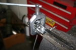 | October 26, 2010 - With the intake done, it's time to work on the brakes.
The master cylinder and the calipers are in place, but every line has to be custom-built. It's not the first time I've done this - I've built the braking systems on two of my cars from scratch and modified a couple of others - but that doesn't make it easy.
I started by picking up a roll of brake line. You can buy pre-flared lengths of line with the fittings already installed, but you get a cleaner fit if you cut and flare your own. I've learned the hard way that brake flaring tools are one spot where it makes sense to spend money. A good tool makes better flares, is easier to use and won't break in half after a couple of tries like a good one.
entry 412 - tags: brakes | | | 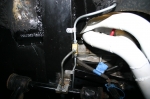 | October 27, 2010 - The front lines are done.
The upper line in the picture drops straight down out of the master cylinder and through the body. The header is pretty close to that master, so I wanted to get the line away from it as quickly as possible.
I originally had a different routing that seemed really clever as I put it together. As soon as I was done, I took a look at it and it was obvious how it should run. So I took it apart again...
The line for this wheel (the left front) joins up with the flex line at the pivot point for the upper control arm. The bracket is actually a Miata part that's originally used to perform the same job on a clutch line. The flex lines are standard Miata parts, and that OE mounting makes for a nice solid connection.
The line for the other wheel is fairly convoluted. It drops down, through another hole in the sheetmetal, over a frame rail, along the back of the steering crossmember and under the oil pan, then back up the way it came to a similar bracket on the right side. Not an easy one to make, but it's done now. The lines are anchored as much as possible to keep them from vibrating. I used some aluminum brackets that can be shaped to fit, but I'm going to keep an eye on them to make sure the brackets themselves don't fatigue.
entry 413 - tags: brakes | | | 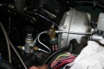 | October 27, 2010 - With the front lines finished, I moved on to the rears.
First, I needed to plumb in the pressure switch for the brake lines and the adjustable proportioning valve. The correct front/rear bias makes a huge difference to the effectiveness of a brake system, so I want to be able to fine-tune it for this particular mongrel. I considered mounting it in the cockpit as I did on a couple of my other other cars, but a street car like this one shouldn't need constant tweaking like those track-biased beasties. Besides, the routing works better this way.
The line from the master takes a bit of an odd route, circling around the body of the master. This gets the line away from the header and also gives me a chance to anchor it down. As an added bonus, it also gives more room for the vacuum line that feeds the booster.
entry 414 - tags: brakes, proportioning | | | 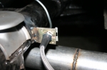 | October 31, 2010 - The brakes are done!
There's one long line that runs from the proportioning valve, over the brake pedal box, through a new grommet in the body, down to the bottom of the footwell, along the outside sill, through another grommet and finally to a hard line anchor like this one by the rear axle. Whew!
Once it gets to the rear axles, there's a tee and the line splits to the left and right rear brakes. Unfortunately, I couldn't figure out a way to run a hard line straight to the calipers. They use a banjo fitting, and the only banjo-to-flare adapters I could find were AN fittings.
This drives me nuts every time I work on brake systems. Modern cars use metric brake fittings. My local auto parts stores only have SAE fittings. And the performance aftermarket only uses AN. It's ridiculous. No matter how much I try, I simply can't use a consistent type of fitting through the whole car.
To make things more fun, SAE and metric fittings use a 45 degree flare. AN fittings use a 30-something degree one. They're not compatible, and you need a separate flaring tool to make the AN flares. So in order to adapt my hard lines to that AN-to-banjo piece, I'd have to buy another flaring tool. I don't know why the racing industry worships at the altar of AN fittings, they're only nice to have if you don't have any production items in the whole car. Otherwise you end up mixing and matching.
So, in order to deal with this banjo fitting on the calipers, I decided to use off-the-shelf Miata flex lines. A flex line is not needed here because there's no relative movement between the axle and the caliper, but they'll do the job and are easily replaced if the need arises. For the connection between the hard line and the various flex lines, I used some brackets off a wrecked Miata. It's interesting to note that this particular design of anchor is the same as used on the MG in the first place. Well, it works!
So, the plumbing is all done. I'll have to bleed them at some point in the future, and then I'll undoubtedly find some problems...
entry 415 - tags: brakes | | | 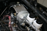 | November 7, 2010 - The braking system is all buttoned up.
The Camaro's vacuum line for the brakes was larger than that of the MG, but a 90 degree elbow with a couple of hose barbs took care of that. It's not the prettiest setup, but I'll sort that out later.
You can also see the convoluted rear line routine - out from the rear fitting on the bottom of the master cylinder, around the master, into the brake pressure switch, into the proportioning valve, then up and over the pedal box to disappear under the fender. Convoluted perhaps, but well anchored and it works.
entry 426 - tags: brakes | | | 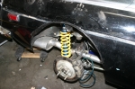 | November 7, 2010 - With the brakes all plumbed in, it's time to bleed them.
Unfortunately, I still have a mismatch of front brake pads (1994 Miata), brake rotors (1994 Miata) and caliper brackets (1990 Miata, which uses smaller brakes). I have a set of the later brackets on the way, but with Janel available to help me bleed I wanted to do something. Well, the Seven was just sitting there with an engine problem awaiting my attentions, and it uses the 1990 size brakes. So I grabbed the rotors and pads from that car and voila! Front brakes.
I've also cut the rear arches away to clear the tires on full bump. There's a double skin to the body here so some black duct tape was used to seal it up until I weld in an insert to join the gap. It was gratifying to see how clean the metal inside that cut section is. That's a rust spot for the cars, and mine was pristine inside. Was.
Time to bleed the brakes! All the suspension pivots have been torqued up and the springs are in place. Does it seem as if I'm working towards something here? Perhaps.
entry 427 - tags: brakes, suspension, body, fenders | | | 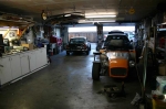 | November 7, 2010 - The brakes proved problematic to bleed.
I think I have one bad flare which will have to be sorted out, and it took forever to get the rears working. But I got them to the point where they'd stop the car, so it was time.
I bolted on the wheels, checked tire pressures, attached the hood and dropped the car to the floor. It's always fun how much smaller they get when they're sitting on their feet. This car's been on jackstands in the garage for a long, long time. The springs are 8" 375 lb in the front and 10" 250 in the rear, mostly because that's what I have. I snugged the spring perches up to the springs at full droop and nailed the ride height almost perfectly.
After a lot of shuffling around and shoving of bits and pieces into handy corners, I was able to free the MG and point it towards freedom.
entry 428 - tags: first drive, brakes, suspension, springs | | | 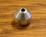 | November 10, 2010 - One step forward, one step back.
Good news - the new tach works! Well, it works once you remember to actually connect the GM tach wire to the MG harness. Interestingly, it seems to read accurately. I didn't have an OBD-II scanner plugged in to read the exact engine speed to confirm, but the car seemed to be idling right around 1000 rpm cold and that's reasonable. I checked the idle at right around 900 after the drive the other day. Interesting - I'd heard the LS engines put out a "four-cylinder" signal, but I figured that was just because a lot of new fours use a waste-spark ignition and thus look more like an 8. Regardless, I'm not going to complain about it! That was easy.
I also spent some time on the brakes. A bit of fooling around and I managed to get rid of a big air bubble in the front of the master cylinder. Voila, a hard pedal! Nice and hard. But the front fitting on the master was still leaking. This will not do. So I pulled it off and yup, the flare looks deformed.
I figured this was probably the case on Sunday when I was bleeding the brakes, but I was hoping that tightening the joint would solve the problem. Of course it didn't, and in doing this I also damaged the seat in the master cylinder - that's it in the picture. No surprise here. Luckily, the seats can be removed so I'll just call Wilwood and order a replacement.
At the same time, I noticed that the master had a big F and R on the outlets. Now, from my understanding, there shouldn't be any difference between them. I did read a blurb in Hot Rod or Car Craft a while back claiming there was and that swapping the F and R lines around solved a soft pedal problem. I still don't understand how - but since I had to rebuild one of the lines to fix that flare anyhow, I figured I'd swap them. This means new lines for both the front and rear outlet, both pretty short but relatively complex. So now I'm back to no brakes at all. Still, I have a clear vision of the way ahead.
entry 437 - tags: brakes, tach, wiring | | | November 10, 2010 - I just got off the phone with Wilwood.
That little tapered seat that is damaged? You can't buy it separately. What an idiotic decision. I know there are giant bins full of them at Wilwood (or wherever this particular master is actually produced), but mere mortals cannot obtain one. Instead, I have to pay for a brand new master cylinder.
Most of Wilwood's masters are just fitted with a 1/8" NPT fitting, and you screw in the adapter you need. If the seat gets damaged, you screw in a different $3 adapter. Not this one, of course.
That is a very poor choice on Wilwood's part. I'll get my replacement, put the current one on the shelf for if/when the master ever needs rebuilding, and look elsewhere for my master cylinders in the future.
entry 438 - tags: brakes | | | November 10, 2010 - There's a new master cylinder on the way here.
I probably could fix the existing seats, especially if I had access to a lathe. But a new master is the safest way to go. Sigh.
The brake lines are bent and my new caliper brackets arrived today, so the brake system will be complete as soon as the master arrives. One more item off the list. Now all I have to do is figure out how to make the emergency brake work!
I also ran into a little problem with the PCV system. A 90 degree elbow rotted away on me. I'll see if I can pick up a generic replacement at the auto parts store.
The current giant rad may have a new home already in a Subaru-engined VW camper. Excellent. I'm looking forward to the new one, I'll be able to drop the top of the rad down by 1" and lift the bottom by 2.5". Better fitment all around.
entry 440 - tags: radiator, brakes | | | 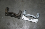 | November 11, 2010 - Wow, the new caliper brackets sure are shiny!
I've never seen a brand new set before, and I'm pretty sure new Miatas don't have that sheen to them. You can see the extra height in the new one, that gives clearance for the larger brake rotors. Usually people source these off a junk Miata, but we're all out at Flyin' Miata and it's not clear when we're going to see more. So I took the easy way out and just ordered these shiny ones. I did have to transfer two rubber seals from each old bracket though.
I did find out why the master cylinder has the F and R ports. There are two pistons inside, and the one closest to the pushrod pressurizes before the second one starts to move. So the first piston should be used on the front brakes. Interesting!
entry 441 - tags: brakes | | | 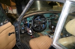 | November 15, 2010 - The interior needs a bit of work still.
Again, lots of dangling wiring. I need to finish swapping over from the MG column switches to the Miata ones which will clear up that particular snarl nicely. I think the tach zip-tied in to the base of the windshield is a nice touch though.
One thing to check off the to do list: brakes. Janel helped me bleed them this morning and the pedal is nice and firm. Just the way it's supposed to be. I do have to remember to bed the pads though, it's easy to forget that when months pass between installation and driving.
entry 455 - tags: interior, brakes | | |  | November 26, 2010 - I don't know why I find this angle so much fun, but I do so you're stuck with it.
After taking the pictures, I bedded the brake pads and headed home. I'm not sure I got the pads hot enough, but I'd prefer to have the alignment done properly before I go too nuts. It'll be interesting to see if the car will align, that will be a moment of truth for my suspension building skills!
entry 477 - tags: testing, brakes | | | November 27, 2010 - Spent some more time driving today.
The loud exhaust drone at 1500 rpm seems to be gone, that's probably due to the exhaust tips. Excellent. It's still not a quiet car, I'm going to work a bit more with the sound insulation and see what I can do there. A lot of the noise seems to be coming through the firewall. There's still some carpet to install, maybe it'll help some.
The ride is also better with the slightly raised height. I'll spend some time tweaking the shock settings, but I suspect it's going to want a bit less rear spring. It has some 250 lb ones now, and I think the lightest I have in the garage is 225. I'll give those a try.
The heater works well. Good.
Janel was driving this time as I monitored the car through an OBD-II scanner. Can't do that with most MGs! Anyhow, she seemed a bit taken aback at the sheer number of creaks, squeaks and bangs from the car as it first started moving down the road. But once she got into the gas, she started laughing. Especially when I reported she hadn't even hit 50% throttle. She likes the car a lot.
Not over-fond of the brakes, as they don't bite too aggressively. The power booster isn't over-boosted and I'm not completely sure the R4S pads are fully bedded. They're also going to be a bit slippery in the near-freezing temperatures we used on the test drive. I am tempted to replace them with a set of Performance Friction PFC 97 pads, which is what I use on the Targa Miata race car. I'll give the R4S a bit more time, as they're usually a good setup.
entry 481 - tags: brakes, test, suspension, exhaust | | | 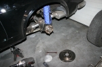 | June 23, 2011 - Before taking the car out again, I had a few other things on the list to fix besides "make it run again".
The brakes were making an odd grumble at very slow speeds once they were warm. Looking at the rear rotors, I saw a weird wear pattern. I'd just slapped on a set of used rotors I had kicking around, I suspect. Since Miata brake rotors are so inexpensive, I swapped in some new ones.
I also spent some time fine-tuning the exhaust fit to keep it from leaning on various parts of the body when it gets hot, checked the steering rack adjustment and did a few other small things. Then I took it out for a run!
entry 599 - tags: brakes | | |
|

 THE DIARY