| LIFE OF A GT |
|
|
 | | January 15, 2010 - A long day with not much actual progress.
I managed to cut out a bracket. Oooo!
Actually, I did quite a bit more than that, mostly planning. I was following a pickup this morning and noticed that the shocks were mounted very far inboard. I realized that this would give more wheel travel for a given amount shock travel, and that I had previously considered a slightly more inboard mounting point on the MG. Obviously I wouldn't want to go too far, as my coilover setup would put some pretty major bending loads on the rear end and the lessened shock travel would mean less precise damping. But would it make much of a difference?
So I dragged the rear end back off the workbench were it was set up to have the shock bracket mounted on the driver's side, and stuck it back under the car. A bit of rough measuring showed that my alternate setup would give me an extra 1/4" to 3/8" of droop. Nothing to be ashamed of for such a simple change, and it would also give me more room in the wheel wells. It would also drop the lower mounting point of the shock down considerably, about 1.5" closer to the ground.
However, while doing my measuring, I discovered I'd mis-measured last time and I really had 2" of droop travel from my expected ride height. I suspect I hadn't let the shock fully extend, these AFCO shocks don't have internal pressurization so you have to actually pull them open. If the damping is cranked up, that takes a significant amount of effort. Regardless of the cause, it appears I have nothing to worry about so I'll continue as planned. The rear end came back out and was reinstalled on the workbench.
While poking around back there, I started looking at other packaging concerns - specifically, the available space for a muffler. There isn't much. The layout of the MGB GT's truck is a little weird, though. There's a fairly tall flat floor. If you lift it up, you discover a cavernous hole that exists to house the spare tire and quite possibly enough tools to disassemble the car. If I move the fuel tank into this space, that opens up a huge amount of room for a muffler underneath. I could either move the existing tank without too much trouble or build my own new one with some baffling inside. Mounting the filler is going to be a bit more of a problem as it would then be about level with the tank, but I have an idea.
More work!
entry 253 - tags: packaging, suspension, fuel tank | | | January 20, 2010 - With the engine back in the car, I determined the final location of the big heavy parts.
In short - quite far back and nicely placed vertically. I'll have just over 5" of air under the sump at my expected ride height, but the hood closes all the way. The shifter is in just about exactly the stock location.
So the next thing to do was to build motor mounts. The passenger's side was straightforward enough, but the driver's side was a real challenge. The mount is extremely close to the steering column, enough that I'm going to have to weld the lowest universal joint to the shaft instead of bolting it on, as there isn't enough room for the bolt to clear the mount. I finally figured out how to put a motor mount bracket in there, but I don't think I can create the lower section until the engine is out.
I did check the clearance on those new headers I brought home. Nope, they won't fit. The passenger's side is good, but the driver's side is not. That steering column again. The headers are obviously from a car that is several inches wider than our little beastie. I can see the possibility of headers that require the removal of the steering column to install - I'll try to avoid that.
The transmission support will take the shape of a new crossmember - pictures to come. I need to make this removable so I can actually take the engine out of the car again, which made everything much more difficult. I'm almost there. This is a very satisfying stage of the build.
entry 256 - tags: motor mounts, packaging | | | 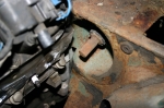 | January 24, 2010 - Next challenge: the steering column.
I'm trying to deal with all of the major packaging problems right now. And this is a good one - the universal joint from the MG that bolts on to this column is so big I can't even slide it into place. It hits the head. As an added bonus, the shaft is a considerably larger diameter than the Miata one at the steering rack.
entry 262 - tags: steering, packaging | | | 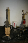 | January 24, 2010 - The first possible solution I came up with to the steering column problem was my standard go-to option.
What about a Miata? So I grabbed a Miata column, stuck a wheel on it (I have at least three wheel adapters and a range of wheels that will fit) and started measuring. Turns out it's ridiculously good.
It doesn't look like in the picture, but the lower side of the bracket on the end of the Miata rack lines up with the location of the firewall on the MG. Easy alteration and the lower mount is done. The flat plate that serves as the upper bracket is actually in exactly the right place. Depending on the wheel adapter I use, the two holes on the Miata mounting plate are in the same place as the MG ones. Well, they're about 10mm closer together than on the MG. But this is a very solvable problem. The third mounting point would be easy to add. And the overall length is shorter, which will move that awkward U-joint further up.
entry 263 - tags: steering, packaging | | | 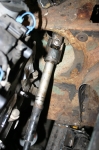 | January 25, 2010 - Just for fun, I checked the length of the lower section of the Miata column.
After all, it's designed to bolt directly into the steering rack. I couldn't believe the result. It's perfect. Not just "close", but bang on perfect. The universal joint tucks into the recessed spot in the firewall, and the rest of the column inside the car is in the correct spot. This could not be better, I really lucked out.
Inside the car, I can play with the final location of the wheel using my various adapters. I'll use the Miata combo switch (ie, stalks) to control the turn indicators, lights and - yet another bonus - the cruise control from the Camaro. I don't think it'll look too anachronistic in the MG interior, and the Miata parts both feel better than the MG ones and give me the controls I need instead of requiring a bunch of extra switches on the dash.
I still can't get over how well this works.
entry 264 - tags: steering, packaging | | | 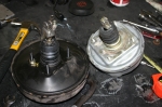 | January 26, 2010 - So, while trying to figure out a few things about the MG booster, it was suggested to me that I try to fit the Miata booster.
As with everything else in this car, make it more like a Miata! Well, my initial reaction was concern that it would fit - the MG part is silver and the Miata one is black in the picture. There's nearly 2" of diameter difference involved.
But I had to try.
entry 266 - tags: brakes, packaging | | | 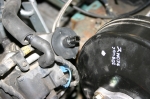 | January 26, 2010 - The booster and the engine end up very close to each other.
Very close. That little port on the head is only about 1/4" from the edge of the booster. It's normally connected to vacuum line that runs from one head to the other, I suppose to prevent pressure buildup on one side.
I looked at a later LS1 and an LS3 in the shop, and I got bitten by the 1998 donor again. In 1999, the heads and valve covers were changed to a center bolt design instead of the peripheral bolt setup I have. This means I can't use a particular Edelbrock coil cover I thought would look great, but that's not important right now. On my engine, both valve covers are the same casting. The little port on the driver's side that's causing me problems is where the oil filler is placed on the other head. On later engines, the driver's side valve cover has a much stumpier protrusion for this port which would give me lots of clearance. This is not a big problem, I'll just whack it off and weld it up. If I decide to keep the connection from head-to-head, I have a few options. So it's not a show-stopper, it's just a bit more work. And it means I'll have to pull that valve cover off - easy to do, just something I was hoping to avoid.
Still, the final result is good. Other than a slightly different pedal ratio, I'm basically running a full Miata brake system. And I know Miata brake systems!
entry 268 - tags: brakes, packaging | | | 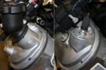 | January 26, 2010 - Here's a peek at where my interference problem is coming from.
The picture on the left shows how the oil filler neck is cast into the valve cover. On my engine, that same casting is fitted with a plastic plug with a vacuum nipple in it. The picture on the right is the newer design, tucking both the casting and the nipple inboard and offering more clearance for applications such as, oh, MGs with power brakes.
After talking with Jon, the V8 tech at Flyin' Miata, it'll be a fairly easy job to make the alterations I need.
entry 269 - tags: packaging | | | February 8, 2010 - I've been looking at muffler and exhaust options as part of my push to sort out the basic packaging.
Essentially, should I run two small mufflers or one medium size one? The goal is to get the car as quiet as possible, as I want this to be a cruiser. If it costs a few horsepower, that's acceptable. The dual pipes (say, 2.5") are easier to package than a single 3" one.
It's not an easy answer. The problem is the fuel tank. It's offset to one side, so to run twin mufflers I'd have to move it sideways. That's not a big deal, but even with that I'd still need some pretty narrow cans. For the single muffler, I'd be looking at a can of approximately 5 x 10 x 17 at most. Luckily, this is a pretty common size range, and I can choose from Flowmaster (excellent website, not a lot of positive comments on the sound from some people), Dynomax (many recommendations for the Super Turbo), Magnaflow (I have one on the Seven, it's so loud it's a running joke locally) and Hooker Aero Chamber.
Based on the recommendations, I think it's down to a competition between the Super Turbo and the Aero Chamber. The fact that the Hooker doesn't have any packing but relies on internal baffling is a bonus for long life. The good thing is that neither one is terribly expensive so I can experiment if I have to. I'd still prefer a pair as part of a dual exhaust, but I just don't think I can make it fit.
Fun stuff, though.
entry 274 - tags: exhaust, packaging | | | 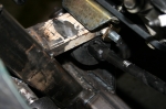 | February 9, 2010 - A peek at the clearance.
This is post-fix, before it was tighter! Installing the steering column is a bit of a pain. I had to lift the engine up, remove the rack, install the shaft on the rack, slide the whole thing back in to place and let the engine back down. I'm trying to make it easy to work on this car, but there's only so much I can do.
That motor mount bracket isn't fully welded yet. That'll happen when the engine comes out next time.
entry 277 - tags: steering, packaging | | | 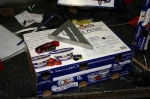 | February 9, 2010 - Check out my new muffler!
Some people use fibreglass or stainless steel wool for muffling, I use yogurt. This box is the same dimensions as a Dynomax Super Turbo, other than the lack of rounded edges. I crawled under the rear of the car and whaddya know, there's enough room for duals! Only barely and I have to move the gas tank over by 3", but I can do it! This is excellent, it means more power and more quiet, both good things. I'll have to figure out how to package an X pipe (and why) so there's some good learning ahead. I think I'll order a single muffler now so I can ensure the fit is good, then go ahead and move the tank.
I've also been researching fuel line parts. What a pain. I'd been hoping to avoid AN fittings but I don't think that will be possible. Our local Parker distributor has gone out of business so that makes my previous plan of using SAE flares more difficult.
entry 280 - tags: muffler, packaging, fuel | | | 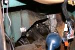 | February 13, 2010 - It's time to start putting some new sheetmetal in the transmission tunnel.
I don't particularly enjoy this part. The driver's footwell was giving me some hassles because it had an odd shape in it - a section pushed outwards. I'm pretty sure this was because the same chassis was used in RHD and LHD configurations, as it gave great footroom if the driver had been a passenger. As it was, it was useless space behind the pedals. Based on my anticipated exhaust routing, I think it'll also be a problem then. So I chopped it off.
By now, the hole has been filled with a flat plate. This makes it much easier to match my new sheetmetal to the straight edge instead of the factory bends, and I'll never miss the space behind the pedals.
entry 282 - tags: packaging, sheetmetal | | | 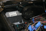 | February 16, 2010 - With the harness simplified, I laid it out over the engine.
Next I had to find a place to stash the enormous ECU. It's huge! Newer ones are smaller - but I don't have a newer one. With the removal of the AC system inside the car, there's some room above the passenger's feet. It would be hard to disguise the big modern heatsinked box though.
The MGB, like many other Little British Cars, is ambidextrous and uses the same chassis for RHD and LHD applications. There are even plates covering over the holes where the pedals would pass through the firewall. This leaves a fairly large space where the RHD pedals aren't, and it's the perfect size for the ECU. As a bonus, the Camaro keeps its ECU in almost exactly the same place so the wiring lengths are almost perfect. I can even reuse the Camaro bracket.
It seems I get lucky with packaging once in a while on this project.
entry 288 - tags: wiring, packaging | | | 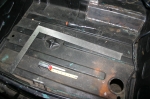 | February 20, 2010 - Before I can start fooling around with the exhaust, I need to confirm that the twin mufflers really will fit.
I'm almost positive they will, but it's time to move the gas tank. This is far less difficult than it sounds. The tank bolts to the bottom of the flat trunk floor. I simply had to drill a number of new holes 3" to the left of the existing ones. The large hole for the filler required a hole saw, but otherwise it was quick and easy work.
entry 293 - tags: fuel tank, packaging, exhaust | | | 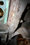 | February 21, 2010 - In order to fit the muffler under the car, I needed to take a chunk out of the wheel well.
You can see it at the lower right of the photo, it hasn't been cleaned up yet. Since the track is now wider than it used to be, this doesn't cause any sort of interference problem with the tires.
I also chopped a seam off the rear frame rail, visible at the top right of the photo. This rail was originally where the rear spring attached, so it saw some decent loads. But with the new coil spring setup, only the bumper is attached back here. By taking off the seam, I'll be able to move the muffler up by about 3/8". Hey, packaging is tight!
entry 295 - tags: exhaust, packaging | | | 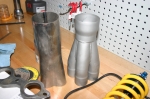 | February 21, 2010 - I've spent the weekend looking at exhaust options, figuring out how it will be routed and what components will make up the final design.
The two collectors in the picture are a couple from my collection. The grey merge collector on the right is an Edelbrock piece, one that I've used before in another build. I only have one of these.
The one on the left is of unknown parentage and will take more work to use as I'll have to cut and weld a star in between the tubes, while the Edelbrock is a slip-on. I have a pair of the basic ones.
The Edelbrock, being a merge collector, will theoretically flow better. But it has a 3" outlet (most collectors don't go much smaller) and I'll have to neck it down to 2.5" almost immediately - I'll use a Flowmaster ball joint connection to do that. So the benefit of the merge collector may be lost. The simpler one is also a 3" outlet, but it'll be shorter in length when assembled. The fact that I already have a pair of the simpler ones makes me think that's what I'll end up using.
I've been trying to figure out how to route the exhaust pipes over the axle. That leaves me short of space for an X-pipe, adds a bunch of bends and gets very tight just behind the axle. The idea is that running under the axle will be bad for ground clearance. But then I realized that the axle at full droop won't drop below the level of the floor pan. This means that if I run the exhaust pipes straight back, they'll clear the axle and ground clearance won't be affected at all! As an added bonus, it'll give me more room to run an X. Excellent. I just put in a big order for exhaust bits that will let me finish pretty much everything but the headers.
I thought I remembered the same thing being done on the Dan Masters build. I checked the photos and yup, it should work.
I have pretty good ground clearance on this car. The lowest point will have right around 4.5" clearance from the ground.
My decision to do exhaust now actually makes sense. It's not as flexible in packaging as some of the other components. Once the exhaust is sorted out, I'll be able to determine the location of the fuel pump and filter as well as the lines to the front of the car, keeping the fuel away from the hot pipes wherever possible. The same goes for wiring. I'm also looking at the cooling setup, but more details will come on that.
This is a really fun part of the build.
entry 296 - tags: exhaust, packaging | | | 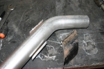 | March 4, 2010 - Now that the driveshaft is done - at least, my part of it is - it's time to take on the exhaust.
This has to pass through a frame crossmember in order to get from front to back, and I realized it would package better if it did so at a 45 degree angle. I picked up some pipe with an ID a bit bigger than the exhaust OD. It's some sort of massive gas pipe, and my poor chop saw had a heck of a time with it!
I sectioned my 45 degree piece to match it to the thickness of the crossmember. To make things interesting, the crossmember tapers in height as it heads towards the sill. So the pipe insert had to be different heights at each corner. Careful measuring, and voila. Ready to weld in once I've cut out the crossmember.
On further reflection, I'm thinking this might actually be best if I leave the pipe as a round pipe. That'll retain more strength (not sure if it's needed here, but still) and will make the lowest point of the car a piece of very burly pipe instead of a thin exhaust pipe. It'll still have approximately 4" of ground clearance, but it's at the breakover point. We'll see, I can always weld this bit back together. And yes, I have considered how I'll remove the exhaust without cutting it up!
entry 302 - tags: exhaust, packaging | | | 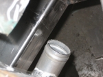 | March 7, 2010 - As usual, everything's tight.
A bit too tight, in fact. When I had the new frame horns and decided to install the rad to show off to Janel what I'd accomplished, I discovered that the radiator outlet was right into the kink in the horn. Argh. So I cut that one off again, chopped 5" off the back end and spliced it into the middle. You can see the ground-down welds in this shot. There still isn't a lot of room for the radiator outlet, but there's enough. That's all I ask.
On the other side of the engine, the alternator has a massive half inch of clearance. Ha, that's miles of room.
Speaking of clearance, I realized that my thought about using pusher fans and moving the rad back wouldn't work. The coolant outlet on the block would get in the way. So nix that idea then. I've decided I'm probably going to use 11" fans instead of the pair of 12" I was trying earlier, as then I can mount them side by side low on the rad. It'll mean most of the airflow will be concentrated on the bottom 2/3 of the core, but since it's a dual-pass setup it'll still hit all the coolant. This gives me more room.
entry 307 - tags: fans, packaging, frame | | | 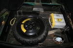 | May 22, 2010 - The batteries (yes, there were originally two) in the MG are supposed to live in some nicely hidden battery boxes just in front of the rear axle.
It's a pretty good use of space, they sit on each side of the differential nose which is easily a wasted area. But unfortunately, my exhaust system just touches the boxes on the bottom. I can raise the bottom of those boxes, but my Odyssey battery is just a bit too tall to allow me to do that.
In stark contrast to that particular packaging cleverness, there's a big empty space under the trunk floor. It originally held a full size spare and, well, not much else. Random tools, I suppose. If I install a space-saver spare in there, there's enough room for my Odyssey battery to lie down in the corner. I'll close in the battery boxes and use them for hidden storage, and this makes a bit of use of that weird basement to the normal trunk.
entry 332 - tags: battery, packaging, spare tire | | | 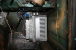 | June 16, 2010 - One of the big roadblocks to the wiring was figuring out how to mount the massive ECU.
As you may remember, I was originally going to put it in the engine bay, but that was a pretty tight fit. I was also trying to reuse the stock bracket, and that was proving to be difficult. There's a bracket from the S10 or some sort of van that is a bit easier to mount in a non-standard location and arrangement, but I finally realized I could simply mount it with a solid strap, as seen here. It's solid and secure, but easy to remove when needed.
The ECU is located at the end of the passenger's footwell, which means the wiring harness can easily drop down through the hole that would have been used for the pedals in a RHD car. Cool. I'll probably put a plate over top of it to hide the ECU and give the passenger a good solid foot rest - but not yet.
entry 347 - tags: ECU, wiring, packaging | | | 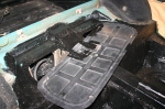 | November 23, 2010 - Lots of miscellaneous work on the car so far today.
I welded in a dead pedal to make life a little more comfortable and to aid in driver retention under enthusiastic conditions. The battery box cover that goes under the rear seat got modified to clear the new bump for the rear axle - that's it in the picture, showing shiny wet paint on the new section. I also removed the parking brake cables for the time being so I can spend more time scratching my head on how to make it work, and built a tie-down for the battery.
Lots of small jobs, most of them rewarding and all leading towards a car that can be used for more than idling up and down the block!
entry 466 - tags: packaging, battery, ergonomics | | |
|

 THE DIARY