| LIFE OF A GT |
|
|
 | | 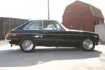 | April 11, 2008 - The stance of the car is a bit off.
Those spring shackles in the rear are likely at fault. I can easily raise the car more, or drill a couple of holes and drop it down. I'll try to find out what the stock center-to-center distance should be and try that. It's hard to say what springs are under there.
See the Aqua wheel wells? That's some sloppy work in the paint booth. 5 minutes with a can of black spray paint and that'll be solved.
entry 5 - tags: suspension | | | 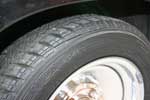 | April 11, 2008 - Not only are the wheels cosmetically challenging, they're also the wrong offset.
The tires and the inside of the fender lips were not getting along, and the steel was winning the battle. New wheels and tires are on the way soon.
entry 6 - tags: intro, suspension | | | 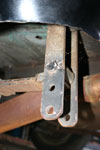 | April 15, 2008 - The back of the car sits quite high.
You can see it in this picture. And this might be the reason. These shackles are very obviously aftermarket, and a quick query on the MG Experience forum (a very helpful bunch) returned the information that the length between the holes should be 2.5 to 4", not the 5+" I have now. If I flip these around and use the bottom hole as the top, I'll get a good idea of if that's too long or two short. It's a distance of just over 3".
I'm guessing a previous owner did this in order to raise the rear and hopefully stop that tire/fender interference.
entry 22 - tags: suspension | | | 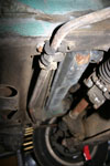 | April 25, 2008 - While underneath the car to change the oil, I discovered the state of the sway (or anti-roll) bar.
Looks as if it was used to drag the car on to a tow truck or something, a long time ago. Oh well, that's an easy fix. I was going to change the bushings anyhow.
entry 48 - tags: suspension | | | 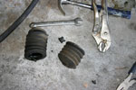 | April 26, 2008 - One of the steering boots was broken, so it got replaced.
Easy enough, although the "precision engineered" replacement from NAPA (it said so on the box!) was anything but. It was a bit of a fight to get the undersized small end over the surprisingly hefty tie rod, but I won. I always win. It's just depends how badly the car has to lose.
entry 49 - tags: steering, suspension | | | 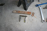 | April 26, 2008 - Time to change the shackles while the car's up in the air.
On top, one of the monster ones the car came with. On the bottom, a stock GT shackle. It's about 2.5" center to center, by the way.
Interesting note - the droop of the suspension doesn't seem to have changed with the new shackles. I suppose that's because it's basically limited by the shock. But it sure compresses a whole lot further. The car sits much more level and the rear wheels are nicely tucked into the wheel wells.
entry 50 - tags: suspension | | | 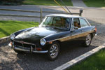 | April 27, 2008 - With the new shackles on the rear, the car sits very close to level.
I haven't checked with a tape measure yet, but it looks right. With the rear wheels tucked into the wells, it's obvious that there isn't room for a massive spacer to move them outboard. It looks much better than it did lifted anyhow.
One thing that's apparent is that something's not right with the rear suspension. It's rock solid, with almost no give at all. I'd swear it was sitting on the bump stops but inspection shows that is not the case. It's not seized, as there's definitely movement when I lift the car. But when I push on a fender I get almost no deflection. I wonder if the aftermarket tube shocks are too long and are bottoming out internally? I'll pull apart a few components and see what I can figure out.
The new grille is fitted, although not yet permanently. The bumper overriders make a big difference visually, so they're probably going to stay. It sure looks a lot better than it did when it arrived! The car's coming together visually pretty well.
entry 51 - tags: suspension, wheels, grille, styling | | | 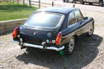 | April 27, 2008 - Time for that all-important first drive!
This is always a big moment in resurrecting an old car. With Basil, it was a late-night run around the block at night with no brakes. Hopefully this one will be a little less exciting.
First off, the car's a bit of a slow starter when cold. I just haven't learned the magic ritual yet. Still, it does eventually roar into life. Yes, roar. There are more holes in the exhaust!
The clutch feels good and the gearchange is really nice. The steering feels good underway, although there's a bit of internal friction. It's as if someone overtightened it to get rid of some play. I'll check that out. The stiff (solid might be a better term) rear suspension certainly affects the experience though. I never knew there were so many bumps on my street!
The brakes have a solid pedal, but need a very strong push. There's probably a bit of rust on the pads, and I think it was getting better. Still, we were mostly cruising along and didn't spend much time on the brakes. I'll bed them in and see if that helps.
The engine seems healthy but the carbs probably need tuning, as the idle never drops down below about 1100. There's also a flat spot on rapid tip-in. Not a big deal, just a bit of fettling required. Oil pressure is strong and all of the gauges work with the exception of the engine temperature.
So, all good then? Well, not quite. The car's spitting out radiator fluid. And it looks foamy. Uhoh. The oil looked fine when I drained it, but either the stock radiator cap is completely trashed (possible) or something's pressurizing the cooling system. I haven't investigated this fully yet. It could be a head gasket, although there's no smoke. Further checking will tell the tale.
On top of that, there are also the usual oddities. The turn signal/high beam stalk is stuck on high beam. There are some weird lights stuck on and others that don't work, so I have to disconnect the battery whenever it's not running. But that's okay, that's part of the fun.
In other words, it's a basically decent little car. It has a list of things that need to be sorted out, but it's all doable and at a good level of difficulty.
entry 53 - tags: driving, brakes, suspension | | | 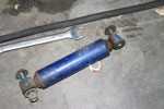 | April 29, 2008 - The mystery of the terrible ride has been solved.
In several ways, actually. I had a suspicion that the shocks might be involved, as they were the most likely candidate for restricting any bump travel. So I lifted the rear of the car up to have a look and whaddya know, one side didn't drop at all. I supported the spring, loosened off the shock and this fell out. It's jammed at full compression. So not only was it preventing the suspension from compressing at all - due to the way it was mounted - but it also was preventing it from moving. So, problem 1 solved.
But there are remaining problems. The shock was fully compressed at ride height, with several inches to go before contacting the bumpstop. Reading the tube shock conversion article in the MG Experience library, I discovered that the lower shock mount was installed upside down. This was probably a good idea given the jacked up ride height originally, but back at normal heights it compressed the shock too much. So, there's a solution then.
Ah, but not so fast. The shocks are a Monroe-Matic Plus 33076, which according to the MG Experience article is the standard Moss shock and is well known for a terrible ride. So I can probably improve on it regardless. The article discussed rooting through parts book and gives a couple of other options. But I can do better! A visit to the Monroe website unearthed a PDF document with all of the mount types, extended lengths, compressed lengths and other good info. A bit of messing around and I turned it into a spreadsheet. So now I can search quickly and easily! I can't tell anything about the damping of the shock, but once I've picked out a few that have more travel than the originals, I'll look up their applications and see what that tells me. Or I'll call Monroe. This is going to be fun.
entry 54 - tags: suspension | | | April 30, 2008 - The shocks have been selected.
Most of my early selections turned out to be for various one-ton vans, with an expected stiff damping. The Mitsubishi Cordia of the late 80's has some shocks that have been used in the past, and they looked to be a good match. There's also a Corvette application that looks interesting, but the 1986 Corvette wasn't exactly known for ride quality!
So, with the application nailed down, I was able to choose between a KYB, Monroe-Matic or a Monroe Sensa-Trac. I went for the Monroe-Matic, as I'd heard the Sensa-Trac shocks have some ride quality issues that may be related to internal gas pressure. The cheaper -Matics are probably not damped quite as aggressively. And they're only $17 each, so what the heck. The total bill was $40 shipped. If they don't work, I'm willing to accept that and chalk it up to experimentation.
The fronts use the same size of shock and I considered picking up a set of four, but I'll put that off until later.
entry 55 - tags: suspension | | | 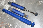 | May 21, 2008 - The new vs the old shocks.
The new vs the old shocks.
entry 56 - tags: suspension | | | 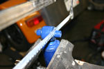 | May 21, 2008 - First step towards installing the shocks - cut down the bushing.
I cut it a bit too far - a touch longer would have worked better with the bolt length. Nothing an extra washer couldn't fix though.
entry 57 - tags: suspension | | | 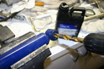 | May 21, 2008 - Step two - drill out the bushings.
They're sized for 12mm metric bolts, but the MG doesn't speak metric. A bit of time with a 1/2" drill, problem solved.
entry 58 - tags: suspension | | | 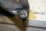 | May 21, 2008 - Either a really stupid idea or a stroke of genius.
The holes in the lower shock mount can get ovaled out and I was seeing the first signs of this. The threads on the bolt were getting damaged as well as doing damage.
So I welded in a clevis pin. It's a nice tight fit in the resized lower bushing so there's no slop, and being welded into place means it's not going to move. Plus it means I can pull out a pin and easily remove the shock. I can hear the purists crying.
entry 59 - tags: suspension | | | June 7, 2008 - It's been pointed out that I never actually updated the results of the shock swap.
Well, the car bounces. That's about as far as I've made it. A few other projects got in the way so the GT went to sleep for a while. Until the Targa Newfoundland car is done with the race, the MG will always be a lower priority.
I did spend some time this weekend at an MG event, though. I was a little busy playing rally driver, but I did get the chance to check out a few nicely finished cars. The grille was well chosen, I think, and a well-finished black dash looks great. So we're on track there.
entry 61 - tags: suspension | | | 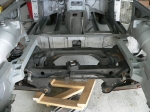 | October 31, 2008 - Of course, a power upgrade of this magnitude will have implications that reach throughout the car.
One victim will be the rear axle. I could cut down a rear from a Mustang or something similar - but why not go with an independent setup? Much more my style. And the obvious choice is a Miata one. I have access to cords of Miata parts, I know how well it works and I can use my access to aftermarket parts to tune the handling.
I'll need a different differential, but that engineering has already been done for the LS1 Miata. So all I need to do is fit the subframe to the car.
Luckily, I have a series of photos showing this being done. Perhaps not with the most subtle techniques, but it's a proof-of-concept. The biggest problem is that the MG's body is narrower than the Miata's, so I'm looking at narrowing the suspension by almost 7". Not difficult, really, but I was amazed at just how much.
entry 65 - tags: rear suspension, planning | | | 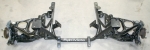 | November 1, 2008 - I measured the maximum fender width of the MG at 58" front and 57.5" rear.
That's a bit approximate, and it assumes the fenders are fully rolled. Measuring a complete Miata subframe with 205-series tires came up with 61" front and 62" rear. So I don't need to narrow things as much as I'd feared, as long as I don't do anything too foolish with wheel and tire choices.
The picture is of a tubular subframe that's made for installing an LS1 in a Miata. I'm not sure if I'm going to cut down a stock Miata part or build a tubular one like this. The latter will be more work - of course - but will offer more room. Remember, I have to narrow the track by about 3".
entry 66 - tags: planning, subframe, suspension | | | November 8, 2008 - After some rough sketches and much thinking, I'm leaning away from narrowing the Miata suspension.
The roll centers won't be as well controlled as I thought - thanks to Jensenman on the GRM forums for making me take another look at this.
Luckily, there's an alternative. The fender flares from a Dodge Omni can be grafted on to the MG bodyshell, adding a bit over 2" per side. That should be almost perfect. Time to start hunting Omnis, or see if I can find another car that would make a good donor.
entry 68 - tags: suspension, body | | | 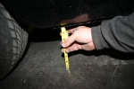 | November 25, 2008 - Before pulling the car apart, I checked to see where the ride height is.
Since the entire suspension is going to be changed out, I want to make sure I put the new on in (approximately) the right place!
While cleaning the garage, I also came across a set of nicely finished Miata wheels - black with a polished lip - that would look good on the car. The Shelby wheels, unfortunately, will have to go due to the 4.5" bolt circle. Like most of the other cars in the garage, the MG will soon have a 4x100 pattern. I'd been eying the Ronal RB as a good option and that might still happen, but for the time being the repainted Miata wheels will do. I can run a 205/55-14 on them, which is about 1" smaller in diameter than MGs usually run. Most people would go for copious rubber in a car like this, but I'll probably set it up to clear some 225s at most and then just run really good rubber.
entry 79 - tags: wheels, suspension | | | 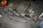 | November 30, 2008 - The next step was to pull the front subframe.
Not a difficult task. It's astoundingly heavy. I forgot to weigh the car before taking it apart (whoops) but it's possible the V8-powered result could weigh less than the original.
I'm starting to reconsider the independent rear suspension. It would be cool to do, but it would be easier - and cheaper - to simply have the Camaro rear end cut down and reworked to run a 4x100 bolt pattern to accept Miata wheels. The solid rear isn't my first choice, but it's how the car was designed to run in the first place and there's a good body of knowledge on locating the rear axle already. Plus, it'll save a bunch of cash and I won't have to redesign the entire rear end of the car.
This car was never meant to be a lap record holder, but it'll end up on track at some point. Hmm. Decisions, decisions.
entry 87 - tags: dismantling, suspension | | | December 1, 2008 - I posted some questions about shortening the Camaro axle to the Grassroots Motorsports forum.
A good bit of information popped up: the Chevy S10 pickup used the same 7.5" rear end, but with a much narrower axle. In the case of the 2WD model, the axle is actually a little bit narrower than the Miata one. That's perfect! It gives me a little more room for wider tires and I'll have a cheap option.
I'll still have to adapt the axles for disc brakes (I can't bring myself to run drums) and convert them to a 4x100 bolt pattern. All possible. I have a good feeling about this, I think it'll be a good solution.
An extra bit of info from the LS1Tech forum - the 1998+ S10 use the same 28-spline axles as my Camaro, earlier trucks use a 26-spline. Very important to know.
entry 89 - tags: suspension | | | 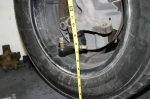 | December 4, 2008 - Time to do a test-fit of the suspension.
In order to get it in approximately the right place, I'm going to set the lower control arm up so a line drawn between the inner and outer pivot points is horizontal. Most people try to set the arm horizontal, but it's the pivot points that matter. So step 1 is to figure out how high they should be off the ground.
I attached an upright to a wheel and measured the distance from the ground (approximately 8.5"), then figured out how high the car was jacked up (10" above normal ride height). So I want my pivot points 18.5" above the garage floor.
entry 90 - tags: suspension | | | 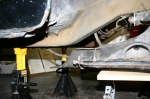 | December 4, 2008 - I can't lift the subframe quite as high as I'd like without cutting something, but here's an idea of the location.
Pretty good, actually. That rear mounting point should actually attach right to the bottom of the stock frame rail. The rails converge and rise in the engine bay, where I need them to spread wider apart. This is going to go fairly well, I think.
entry 91 - tags: suspension | | | 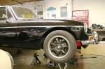 | December 4, 2008 - Of course, what I really wanted to know what how the wheel looked on the car.
Would my painted Miata wheels suit it? How far would it stick out of the fender well?
The answer is that it looks good. I like it. The tire diameter is 23" instead of the stock 24" on the MG, but I can probably live with that. I can run a 205/55-14 RA-1 (or some similar R-compound) to give me good traction without having to use a ridiculous tire size, and a 225/45-15 is a future possibility. The fact that I have a set of the RA-1s on these wheels in this size already is just icing on the cake.
entry 92 - tags: suspension, tires, wheels | | | 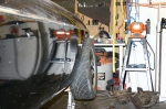 | December 4, 2008 - The tire does stick out a bit.
About as much as I'd expected based on my measurements, which is reassuring. A rough test fit shows that the Rabbit fender flare covers it almost perfectly. I'll pull one of the RA-1s off and test fit with that as well, but I have a good feeling about this - as long as I stick close to the stock +45 wheel offset, anyhow. I should probably make sure the +30 wheels with 205/50-15s fit, as that's what half of my race tires are.
The fairly radical camber is because I assembled this suspension out of spare parts and everything's just finger-tight. No attempt at alignment has been attempted!
entry 93 - tags: body, flares, wheels, tires, suspension | | | 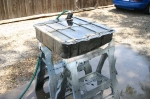 | December 10, 2008 - Before I spend too much time obsessing over the engine, I need to get the car's suspension in place.
That's a fixed location, unlike the engine which has a bit of leeway.
Basically, what I'm going to do is to hollow out the engine bay. The frame rails will come off, along with the inner fenders. That's not a big loss on the passenger's side, it was hammered very hard to clear that massive AC compressor years ago.
Once the bay is empty, I'll rebuild the frame rails with the right geometry to mount my Miata subframe. They're going to look quite different, but they'll attach up to the factory ones under the car if my tape measure is telling the truth.
Before any of this can start, however, I need to empty out the bay a bit more. So I'm pulling all the brake lines, clutch lines, wiring and miscellaneous parts. I've also reinstalled the radiator support to provide a bit more strength to the front of the car during surgery, and welded a couple of posts to it to prevent things from sagging.
entry 103 - tags: suspension, frame rails | | | 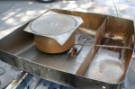 | December 10, 2008 - Turning my attention from the front of the car to the rear, this showed up today.
It's the rear axle from a 2000 Chevy S10 Blazer 4WD. The width is 59", 4" wider than the 2WD rear and a nice match to my front track. I've pulled the brakes to replace them with Miata parts, which is going to involve a bit of bracketry. Still, nothing too exotic. There's also going to be a lot of cutting of old suspension brackets and welding of new, of course.
I wasn't sure if this was going to be a limited slip or not. Experimentation would indicate not, and changing to the Camaro rear will mean setting up the pinion again. Oh well, it's another skill to learn.
entry 105 - tags: suspension, rear axle | | | 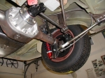 | December 10, 2008 - So, how do I locate the rear axle?
Hanging it off leaf springs just isn't an option for ride, handling and tuning ability. So I'll change over to coilovers and a multi-link setup. Lots of learning here, I've never had to deal with a big stick axle before.
This is a three-link setup as sold by Fast Cars, an MG conversion specialty shop. It would be easier to design and build than a four-link, especially with these photos. However, I'm not too excited about the concept of a panhard rod and the slight lateral movement of the axle it creates - and I'm really not a fan of that bent rod in the Fast Cars kit. This car won't spent a lot of time on the track, but you know it will happen!
More photos of this particular car can be found on BritishV8.org - it's a very thorough conversion and you get a really good look at the suspension design and brackets.
entry 106 - tags: suspension, design, 3-link, rear axle | | | 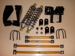 | December 10, 2008 - The other option for the rear is a four-link setup.
It's a little more elegant from an engineering standpoint - the axle is nicely constrained. But it's more of a challenge to design well, as there's potential for binding. I have to admit I'm not completely sure how to design that, or if it's really a risk. I've been running the kinematics of both designs in my head all day, trying to figure it all out.
The picture is of a commercially available kit from Classic Conversions, and it's actually designed to bolt into the chassis. Pretty nice. According to a writeup (with more pictures) on BritishV8.org, it's designed to have a bit of roll oversteer which is something I'd prefer to avoid. Still, it's a good option - although with a price of over $1000, it's more likely that I'll use it as a proof-of-concept.
entry 107 - tags: suspension, rear axle, 4-link | | | December 15, 2008 - Not much actual work on the car, but lots of planning.
I'm going to go with a three-link rear after talking with a number of road racers and other folks on the Grassroots Motorsports forum. The lateral motion of a long Panhard bar isn't a big deal at all it seems, and it's free of bind and easy to fabricate. So there's that settled. I just have to do it!
I'm also starting to plan the brake system. Very little of it will be MG by the time I'm done. In fact, it's possible it will all be custom. I'll have to wait until the motor position is determined before I can finalize this but it's fun to build it in my mind. Brakes are important to me, and I like putting together good systems.
This is actually a very entertaining part of the build. I have all of the major components so I can start legitimately planning and figuring out how to do things. On top of that is the anticipation of the first big steps coming up - I'm looking forward to that first chop of the frame rail with anticipation and a little frisson of nerves. This is the stage where the whole car comes together in concept, making it a complete machine instead of just a collection of bits that are a reaction to unforseen problems.
I love this part.
entry 108 - tags: suspension, brakes, rear axle | | | 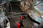 | December 31, 2008 - It's been a long break over the holidays, but I wasn't able to get much accomplished due to visitors.
Still, I snuck away for a few moments here and there. At the moment, I'm still trying to figure exactly the best way to mount the suspension. First I need to make sure I have the centerline of the car marked. Here, I'm taking the center of the stock crossmember mounting points. I dropped a plumb line down from that X and marked it on the floor. After doing that with a few more locations, I'll have a good record and will be able to chop out the original frame rails.
entry 109 - tags: suspension | | | 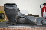 | December 31, 2008 - Here's a side view of a stock Miata subframe.
I've spent some time measuring it and poking around under the car, trying to figure the best way to mount it. The original plan was to build new frame arms - that's what the other Miata-suspended GT got, although that setup never got beyond the very first stages.
But really, I don't need to mount it. I just need to mount the control arms and steering rack. Hmm.
entry 110 - tags: suspension | | | 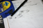 | December 31, 2008 - As much as I hate the thought of a ladder frame, it might work out.
The original frame rails are at almost the perfect width to let me mount the control arms directly to them. Add an extension at the front to hold the upper control arms and a cross-piece for the steering rack - and voila. The upper arms don't see as many side forces as the lower ones do, but they do see forward forces under braking. The whole thing will probably be more prone to twisting as it's only in one plane, and I'm still concerned about a good upper mount for the shocks. So maybe it does make most sense to continue with the previous design. But it's an interesting possibility.
This tubular subframe actually makes it look like a pretty good option. I'd basically do the same thing, except it would be welded to the frame of the car instead of bolted.
entry 111 - tags: suspension | | | 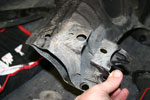 | January 3, 2009 - Now that I've figured out how I'm going to deal with the front suspension, it's time to get cracking.
Lots of measuring and calculating and general head-scratching, and it culminated in this. The donation of control arm brackets (with alignment capabilities) by a stock Miata subframe. The sawzall got a real workout today. That's foreshadowing!
entry 122 - tags: suspension | | | 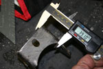 | January 3, 2009 - I've decided the best way to run the rails is just inboard of the stock ones.
That'll let me run them back to the middle of the car (where the stock ones stop) and tie them in together. More strength for the car!
This puts the outside edges of the rails 570 mm apart. To put the brackets in the correct place, they need to be 38.5mm at this dimension. Not bad for cutting with a relatively blunt instrument, no? I'll clean them up a bit on a belt sander before welding. The dimension isn't critical to the half millimeter (0.020" for those who speak the old language) because there's a significant amount of adjustment room in the control arms - but it's good to be fairly accurate here if possible. I'd hate to run out of adjustment for the alignment.
entry 123 - tags: suspension | | | 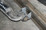 | January 3, 2009 - A view of the bracket on the new frame rail.
The new rails are 2x3" 18 gauge, which is significantly bigger than the stock stuff. Fair enough, there's a lot more running through them! I'll have lateral bracing wherever I can fit it, as well as a bit of vertical to stiffen things up.
After much measuring and poking around and measuring, it turns out that the correct height for the control arms is serendipitously right in the middle of the frame rail. I played around with heights ranging up and down a couple of inches, and this puts them 7" from ground level. That's 1" higher than the ones on Janel's slightly lowered Miata, making the geometry just about a perfect match for a stock Miata.
entry 124 - tags: suspension, ride height | | | 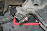 | January 3, 2009 - The brackets for the front control arm pivot point aren't as conveniently designed to be cut off as the rears are, and the bushing is wider.
So I took a rear one and cut it in half. Yes, I'll need another Miata subframe to supply me with enough raw material, but that's not a big problem for me.
entry 125 - tags: suspension | | | 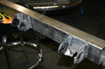 | January 4, 2009 - Now I feel like I'm making some progress.
It's no world-changing piece of fabrication, but the lower control arm mounting points are in place on one of the frame rails. This is the first constructive step of the project, everything else has either been preparation or destruction. A few more of these sorts of changes and the car will be ready to drive!
entry 130 - tags: suspension | | | 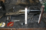 | January 9, 2009 - Time to build the brackets for the upper control arm.
Step one, get my hands on a front subframe that doesn't have the rear mounts hacked off. Oops! Luckily, there was one in the metal dumpster at Flyin' Miata.
Step two, build a jig to locate the upper control arm mounting points in space. This isn't exactly a production quality jig, but it'll do for a one-off. It's accurate, which I tested by removing and replacing the stock piece a few times. A couple more pieces were added after this picture was taken, but you get the idea.
entry 131 - tags: suspension, frame, jig | | | 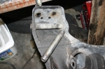 | January 9, 2009 - The upper arm is bolted onto this tube.
It's a metric size, and there's nothing quite right available off the rack. I don't want any slop in the long bolt that runs through the tube for obvious reasons.
So I went back to the sacrificial subframe and chopped one out. Here you see the before and after. There's an amazing amount of weld on this tube, there was lots of grinding involved.
entry 132 - tags: subframe, suspension | | | 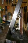 | January 9, 2009 - Here's a rough approximation of how the upper mount will be supported.
A section of the same 2"x3" square tube that makes up the chassis rails will go up and out, and extend beyond the upper arm mounting to provide the upper shock mounting location. Some fore/aft bracing will be added later, and I'll run something from side to side at the top if the engine allows. The base of the bar will also move closer to the center of the frame rail, this is mostly just a convenient place to sit it right now.
I could mount the bar like this, with the upper arm mounting tube welded to the side of the bar. That gives a slightly better location for the shock mount.
Another option would be to angle the bar more and run the tube through the center of the bar. That would be stronger for the tube, but less ideal for the shock mount. Since the shock mount is going to get big loads (the vertical loads from the car go through it while the upper arm mostly has to deal with some side loads and a forward load on braking), I'm thinking the first option might work better.
I'm starting to wonder if I'm going the wrong way here. Should I have the frame rails kick upwards after the firewall, supporting the lower control arm mounting points with a crossmember that dips down under the engine? I'm worried about twisting loads coming from that upper shock mount located so far away from the rail. I could tie into the body, but there's not really much there. Then again, the Miata doesn't have a whole lot of metal in that area and there are no side loads on the shock due to the double wishbone configuration. Meanwhile, the lower control arms take the brunt of the cornering loads from what I understand. Hmm.
entry 133 - tags: suspension, frame | | | January 9, 2009 - While looking around to examine various frame designs, I came across this ambitious project.
A Miata stuffed inside an Morris Minor. I've seen it in the past but had forgotten about it. And check it out, there's the same suspension setup I'm working on. No pictures of the final product which is a shame, but there are some good ideas in there. I like the wood mockup.
entry 134 - tags: suspension, frame | | | January 10, 2009 - Okay, I think I have it.
The crossmember to mount the steering rack actually has to go directly in line with the front lower control arm mounts. I can use a plate or some bars to triangulate the upper mount points to this, getting rid of my twisting problem. It's still a ladder frame with the torsion problems that implies, but a full space frame isn't going to happen at the front of this car.
I'm going to keep thinking about this, both how to implement with the lower control arms as-is and how to deal with the upper location, but I think I'm on the right track.
entry 135 - tags: suspension, frame | | | 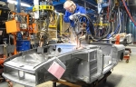 | January 11, 2009 - Ooo, a naked MG!
This is from the very cool British Heritage website. From this and other pictures, I have a better idea of where the various beams and strong points are to be found in the body shell. For example, there's a beam at the top of the fender that I'd never noticed before.
I'm going to triangulate my suspension pickups off them, making a pseudo-spaceframe out of the front end. I have a number of the new tubes figured out, but I won't sort out their final locations until the engine is in place. I suspect a few of them will have to be removable as well to deal with engine serviceability.
One thing that occurred to me yesterday is that the high frame rails with a dropped crossmember for mounting the lower control arms won't work with Miata geometry. The front and rear pickup points are a long way apart, and the crossmember for the rear one would go right through the oil pan. That's not good.
entry 136 - tags: suspension, frame | | | 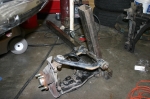 | January 11, 2009 - It doesn't look like much after all that work.
Still, here's the first corner of the new frame. When I look at it in the car, I realize how short many of these distances really are. Most of the length of this bar will be welded to the bottom of the car, both to the floorboard and tied into the existing frame rail. It's not going to be difficult to make everything stiff and solid. I spent most of my working time today finishing some of the design work in my head, and I'm pretty happy with it all. This is just a skeleton.
You can barely see it in the picture, but the upright is welded to the front suspension pickup. I'll add in an extra triangle to help spread the forces around as well as tie into the crossmember that will support the steering rack. The upper end will be tied into the top of the fender and the beam in there, as well as back to the firewall on a bit of an angle. I'm also planning a little more bracing to tie the upper control arm mount to the upright a bit more - nothing complex.
The one mistake I made was that I didn't cap off the end of the upright, and it's going to be tough to do now. I don't really want to leave it open to the elements either. Whoops. It's possible to do, but it will be awkward. Then again, there's no chance of water getting trapped in there now! Is it better to make it watertight (hopefully!) or to make it irrelevant if water gets inside?
entry 137 - tags: suspension, frame | | | 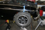 | January 14, 2009 - It's time to put some suspension on the car.
First, I need to identify exactly where the wheel will go. The centerline was marked with the plumb line. Then I took a measurement from here to the crossmember under the car, where my new frame rails will terminate. As do the originals.
entry 139 - tags: suspension, frame | | | 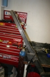 | January 14, 2009 - In order to fit the new frame rail to the bottom of the car, it has to be cut to match the contours of the floorpan.
There are enough little dips and lips to make this a real pain in the butt, actually. Lots of careful measuring and turning parts around in my head, then it was time to cut.
entry 140 - tags: suspension, frame | | | 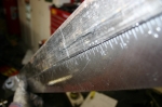 | January 14, 2009 - All that careful measuring, and I cut with a Sawzall.
Actually, it's possible to be pretty accurate with one. Check out how straight that edge is! I can't do that well with a bandsaw.
entry 141 - tags: suspension, frame | | | 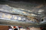 | January 14, 2009 - Before I could attach anything, I had to clean off the frame rails.
That's some good looking metal for a 37-year-old British car! I used a wire wheel on my angle grinder to clean it up. Really, I don't need to clean up the side of the original frame rail as I can't weld to there, only the edge.
entry 142 - tags: suspension, rust, frame | | | 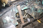 | January 14, 2009 - After innumerable test fits, small tweaks and a wholesale chop of a 3/4" strip down one side, the suspension is ready to weld in.
Note how the upright goes right into the front fender. It lines up nicely with the support behind the fender. So that's good!
You can see the angle level I'm using to make sure everything is correct. After all that test fitting, I still ended up with a surprising gap between the top of the rail and the floorboard. I'll fix that either with a piece of small angle welded in (which will actually provide a little more stiffness, I think) or by persuading the thin floor to move slightly. It's not far off, but it doesn't take much for a weld to be a problem. I'm also probably going to have to see if I can remove the asphalt sound deadening from the floorboards. Now that is going to be a pain.
Everything's just welded enough to hold it in place, although I can't call some of those welds under the car tack welds. They're pretty beefy. The ones at the top of the upright are tacks, though.
entry 143 - tags: suspension, frame | | | 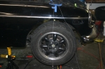 | January 14, 2009 - So, how did the wheel align after all that?
Almost perfectly. It looks like it's moved forward slightly from my ideal, but not enough that anyone will ever notice. The only problem is that according to my angle level, I don't have much negative camber. I think I'll move the top of my upright inboard just slightly, enough to move the adjustment range more into the negative range. Before doing that, though, I'm going to measure it again tomorrow. I should tighten all the suspension bolts more first to make sure I'm getting accurate readings, they're all just finger tight right now.
The suspension has lots of room to move and it's all nicely fixed to the car. Some extra braces will be coming to reinforce the upright, but this is enough to get me started.
Now I just do the same (only faster!) on the other side of the car, then put the crossmembers in. And with that, I can start to figure motor mounts, steering column routing, wheel flares and a bunch of other items. Here we go!
entry 144 - tags: suspension, frame | | | 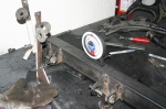 | January 18, 2009 - It was too nice a day outside to work much on the MG.
But I did get the left front suspension started. Here it is in the highly professional jig for the upper control arm placement.
I assure you, the welds look much less dodgy in person!
entry 148 - tags: suspension | | | 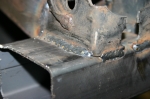 | January 19, 2009 - See?
Not so bad.
entry 149 - tags: suspension | | | 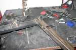 | January 19, 2009 - The left front suspension is all together.
So tomorrow it'll get welded to the car. Then the steering rack support - and then I'll be able to steer the wheels! How exciting.
entry 150 - tags: suspension | | | January 20, 2009 - Whoops.
I got the second frame rail cut to shape and tack-welded into place. Then, just to check my placement, I checked the horizontal distance between the front control arm mounting points.
They were about 10mm too wide.
That's odd, how could I have made that miscalculation? Just for fun, I checked the distance between the rails at the front. Again, about 10mm too wide. But the rails were pushed up tight against the inside of the stock rails, so how could that have happened? A bit of head scratching and then I checked the width of the rails at the firewall. Perfect.
They're splayed.
So I crawled back under the car again to see if one wasn't butted tight against the stock rail, but both were good. Sighting along the new rail showed me the problem, though. The rails weren't straight. In my excitement to put the suspension pickups in place, I'd managed to warp them. Obvious in retrospect, not something I expected at the time. At least it appears I did it nice and evenly, but this isn't good.
So I think I'll try heating up the inside edge of the rails and see if they pull back straight. It's a trick I learned from an exhaust shop - heat up the steel and let it cool, and the hot side will shrink down a bit. Basically, do the same thing that bent them in the first place. Either that or I cut them loose and start over, or cut and weld the rails with an angle correction. Ugh. I'll try heat first.
entry 151 - tags: suspension, frame, ok | | | January 21, 2009 - Some more thinking on the frame rails.
I'm going to replace them, and I'll take the opportunity to bump the wall thickness a bit. Just because. The mounts will get cut off the existing rails and welded on. I know how I can do this without needing to go through all the fixturing again.
This is the smart choice. I was trying to think of easier ways, but it'll only be another couple of hours worth of work, and it's the strongest and best solution.
entry 152 - tags: suspension, frame | | | 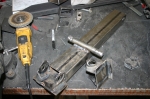 | January 26, 2009 - After a fairly short and noisy period, the frame rails were removed from the car.
I then proceeded to chop them up and remove the brackets. Voila, ready to weld on to the next rails. Slowly, without too much concentrated heat. The only thing I have to worry about is getting the brackets the correct distance apart, and for that I'll simply weld them in with a lower control arm in place.
In other news, I took the Camaro in to work today. Everyone was surprised, as they assumed it had been gutted some time ago. Far from it - they're much more compact when fully assembled! I'll order a coolant temperature sensor tomorrow so I can make sure the temperature problem is sorted out before the engine goes in the new car. And I also noticed the big black car has cruise control. Hmm, how could I integrate that while making it appear completely vintage? That could be a pretty cool addition...
entry 153 - tags: camaro, suspension, frame | | | 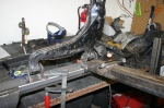 | January 28, 2009 - I picked up some more steel for the frame rails.
This new stuff has a thicker, 11ga wall and is hopefully straight. Step 1 was to weld on the front control arm mounting point, then I bolted up a control arm and used that to fixture the rear. Quick and easy. The relationship between the lower and upper control arms is handled by the fact that the front mounting point remained fixed to the upper one.
entry 154 - tags: suspension, frame | | | 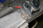 | January 28, 2009 - To minimize the chances of warping, I moved around the pieces to weld them.
The idea was to never let one area get too hot. The thicker wall also helps here.
entry 155 - tags: suspension, frame | | | 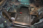 | January 28, 2009 - With the frame rails assembled, I cut them to shape to fit the floorpan, then tacked them into place.
They went in quite satisfactorily and with the angles all looking good. Then, to make sure, I stuck the steering rack crossmember in place after cutting it from a calculated (not measured) length. And it fit perfectly. Everything looks to be centered and the dial level is happy. So we're good! That didn't happen right away, I had to play around with it all for a bit until it all just clicked into place. Sharp eyes will notice that I did have to cut a slot in the frame rails and weld it up, using that to take out a small bit of warp from the welding. It's minor, but spread over a 4' length even half a degree could be problematic. But it's all good now!
I just need to fully weld the frame rails on, then I'll come up with some steering rack mounts. Then, once I know where the steering shaft will run, I can start reinforcing and integrating the new frame into the unibody. I'll also start massaging the transmission tunnel to fit the (huge) T56 transmission.
I feel as if I just unlocked the potential for a large percentage of the project to move ahead.
entry 156 - tags: suspension, frame | | | June 19, 2009 - I welded the new frame rail to the car last night.
It's not really a frame rail, most like a lower suspension mounting point that's two feet long. But still. 30 or so rosette welds plus a solid connection at each end, I think it should work well enough.
It sure looks weird peeking under the car and not seeing any visible connection between this new rail and the floor. But I know it's there!
entry 188 - tags: frame, rear suspension | | | June 25, 2009 - I just realized that I goofed.
I picked up some nice 4-bar ends from Speedway Motors a while back to serve as the ends of the various suspension arms. I prefer these for a street car because they'll be quieter than the more typical rod ends. Hopefully I can get replacement bushings for them! Anyhow, I ordered 6 without realizing that there's a left-hand thread version. The latter is pretty hard to find on the Speedway website and I only stumbled across it after some pretty determined digging.
And of course, the pretty swaged steel tubes I was going to use for my chassis arms come with a right/left thread. So I've ordered 4 of the left hand ones now - I've decided to use a pair on the Panhard rod as well as the trailing arms. I'll have two right hand pieces left over when I'm done, but such is life.
Meanwhile, parts are coming in. A set of ARP studs for the new axles arrived today (Camaro ones that cost $12.00 for a set of five, it's not worth buying stock Miata ones for that!) and the axles themselves should be here tomorrow. Once I have them, I'll mount up some wheels and figure out the exact axle location.
Meanwhile, I've been under the car and realized I'm going to have to do some more cutting around the rear bulkhead to make room for my center link. No worries, it just means more time under the car getting showered in metal shavings. The second pickup point is also welded into place now.
entry 189 - tags: rear axle, suspension | | | 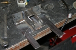 | October 26, 2009 - The book is done, so it's time to tear back into the MG.
Janel's been asking when I'd start working on her car again, and with a day off the answer was "today"! This is the new mounting point for the upper suspension link. I've been basing my design on the Fast Cars three-link used in the well-documented build of Dan Masters' Ford-powered car. I'm not as pretty a fabricator as those guys are, and I was definitely cursing my lack of a bead-blasted and pristine shell today as I cut brackets off around the battery boxes. Yuk.
From what I can figure, this thing will mostly see tension as the diff tries to rotate upwards. The Fast Cars solution includes a reinforcing brace along the top of the transmission tunnel which seems like a pretty good idea. The only downside is that it would require custom carpet, and I'd much rather deal in metal. I'll probably put something similar in and solve that problem later.
entry 199 - tags: suspension | | | 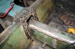 | November 4, 2009 - Time to attach the suspension mount.
I'll weld around the edges as best I can, but I also added holes so I could use rosette welds to attach it to the bulkhead. The rectangular hole - after a bit of cleanup - is where the transmission tunnel brace will go.
Poor MG.
entry 202 - tags: suspension | | | 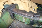 | November 4, 2009 - All attached!
The bracket was welded in, then the tunnel reinforcement was welded to the bracket and then to the tunnel. I was simply going to stitch weld this into place, but, well, I got a little carried away. I'm not worried about this coming apart, I think the whole car will be stronger for it.
entry 203 - tags: suspension, bracing | | | 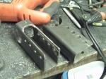 | November 7, 2009 - After a certain amount of noise in the garage, I've finished the axle brackets for the lower trailing arms.
I gave my self multiple holes so I can play the geometry, but the second from the bottom is the one I'm planning to use.
Things are starting to come together on the suspension setup. The MG had a travel limiting strap, and the mounting bracket is well placed for the shock mounting and I can put the shock mount on the back of the lower trailing arm brackets. I'm not sure the upper will be strong enough so I'll probably reinforce the bracket. All this will give me enough room to comfortably run a shock with 5" of travel.
I'm also going to use the bumpstop mounted on the frame so I don't rely on the bumpstops on the shock, which will also take some hard impact loads off that bracket. It does mean I'll have a hard rubber bumpstop, and I'd prefer a softer setup. But I'll see what I can do about that down the road.
So, plan of attack. Build the mounting bracket for the upper link, then weld all the various brackets on the axle. That'll be fun - the center one will be welded to cast iron, which is not something I've done before. I also have to be careful not to warp the axle housing with the two lower brackets. Once I have the brackets on, I'll confirm the length of the arms and order the swaged tubes for the arms. Then I'll be able to move the suspension through its range of travel and figure out the best way to run the Panhard rod.
entry 204 - tags: suspension | | | 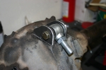 | November 10, 2009 - The bracket for the center link has been fabricated.
Now I just need to stick this thing on there. The housing is nodular iron, a sort of cast iron that's more ductile than the really cheap stuff. Much easier to weld from what I understand, but it still takes more effort than just hitting it with the MIG.
From what my research tells me, the easiest way to weld it is with a stick welder. I don't know how to stick weld (yet) but my friend Brandon is willing to help out. I picked up some nickel rod today for the job. It's also important to minimize the thermal shock to avoid cracking. We'll pre-heat the housing with a torch before welding and use the torch to keep it hot after the bead is laid down. We'll see how this works.
I also finished a bit of welding on the center bracket on the body. It's not all that pretty, but it will do the job. That puppy is not coming out!
entry 205 - tags: suspension | | | 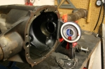 | November 12, 2009 - Time to weld the brackets for the lower arms to the axle housing.
Of course, the housing is round and there are many ways I could stick the parts on them crooked. The back of the differential housing is perpendicular to the pinion, so I set that up to be vertical. A Miata jack under the nose of the housing let me finely adjust the angle. The arms were also set up to be level.
After all that welding in and under the car, having the pieces sitting in front of me on my solid workbench is a real luxury!
entry 206 - tags: suspension, rear axle | | | 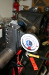 | November 12, 2009 - With the housing properly located, I did a bit of final fitting.
The brackets need to be 905mm apart on the inside edge and vertical in two planes. A bit of careful work, some solid tack welds and voila!
Except I made a mistake. The brackets on the chassis aren't designed to use washers. These are, and I forgot to take the thickness of the washers into account. They're right around 3/32" thick, so I have the brackets 3/16" too far apart. Argh. Is that enough to be a problem? Will I have to cut the brackets off and move them? I don't know. I'll get the tubes and test fit, and see if there's any sign of binding. I have a couple of ideas that don't involve the grinder, but that really would be the smart solution.
entry 207 - tags: suspension, rear axle | | | November 17, 2009 - Of course, after all that measuring and checking, one of the lower brackets was a bit crooked.
I'd been quite careful to align everything, but one must have shifted as I tacked it on. It was about 1.5 degrees off where it should be, but was visibly crooked. The human eye is unforgiving!
It didn't take long to cut it off (that's why they were only tacked on securely instead of having the full bead applied) and reposition it. So there's that solved.
Once that was done, I slid the axle under the car and supported it on jackstands at the normal ride height. I then measured the exact distances from the brackets to the chassis so I could order the right parts from Speedway Motors - some swaged steel tubes with both left and right hand threads so that adjusting is a snap. Besides, the tubes are the same price as one weld-in bung for making your own! I did pick up a couple of those so that I could make my own Panhard bar, though. It'll be longer than the tube lengths, and this way I can use a larger diameter tube for more stiffness over the longer length. I'm going to make it as long as I can to minimize lateral movement of the axle through the suspension travel. Anyhow, I should hopefully have those parts on Friday so I can actually attach the axle to the car! At which point I will undoubtedly discover something terrible.
I also measured my planned shock mounting point. Hmm. If I want to use that location and retain a shock of any significant travel, I'll have to extend my lower brackets down further. This will put the bottom of the shock about 4" from the ground. Not really a problem of course. I do have room to put the shock in the wheelwell with my current axle, but that may limit my options for more tire in the future - I'm considering narrowing the rear so I can run wider rubber. If I do extend the lower brackets, I can either weld an extension on to the existing ones or chop them off and build another set that's longer. I'd probably go with the latter, it's the smart way to go.
One piece of good news - looks as if there's enough room for the Panhard rod behind the axle. Excellent. This means it can be straight instead of having to bend where it goes over the diff, and thus will be stronger.
entry 209 - tags: suspension | | | 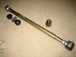 | November 19, 2009 - A big box full of MG suspension parts arrived in the mail!
Well, I know they're MG suspension parts. Most people probably wouldn't identify them as such.
A collection of swedged rods for my trailing arms along with 4 left-hand thread ends. I'm sure I ordered the latter back in the summer, but they're nowhere to be found. At worst, I have some spares.
I also picked up a couple of weld-in bungs so I can build the Panhard bar. I'm pretty close to that point. Cool.
entry 213 - tags: rear axle, suspension | | | 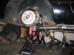 | November 20, 2009 - The axle in its new home!
It took a bit of fiddling around with trailing arm length to get it in just the right place, and I think I'm going to have to pick up some lower ones that are an inch longer. No worries, they're only about $12 each. I'm actually really liking these, I'm trying to think of other cool places to use them. It's super-easy to adjust the pinion angle and the rear axle angle.
In this picture, I have the jackstands at different heights - the arms are usually parallel! I also took the shot before I went on a major garage cleaning binge. That's how it usually works, right?
entry 215 - tags: rear axle, suspension | | | 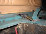 | November 21, 2009 - With the axle actually attached to the car, I was able to move it through the full range of motion.
As I suspected, at full compression the upper link hit the bottom of the car. After a bit of fine metalwork, I had that problem solved! Right now, maximum compression is actually a bit more than was available on the original suspension. My tires are a smaller overall diameter but since they're further outboard, getting this much travel is going to involve quite a bit of surgery to the wheel wells before the fender flares go on. The plan to to build the car to allow this much travel, then use spacers to limit it to less if that should become necessary for any reason.
It was very cool to be able to put the axle through its paces and see how things worked, then simply reach up and tweak the pinion angle or the fore-aft location.
entry 216 - tags: rear axle, suspension, travel | | | 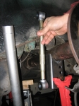 | November 21, 2009 - I'm still playing around with places to put the coilovers.
This rod is the same length as a fully compressed AFCO shock with 5" of travel. With the suspension at full compression, it helps me determine my worst-case scenario for mounting points. I'm starting to lean towards putting the shock in the wheel well. It'll take up a bit of space that could be used for tire, but on this axle there aren't really any options for moving the tire inboard much anyhow. As long as I have an inch or two of clearance, it shouldn't cause any real problems.
If I do decide to narrow the rear axle to allow more tire - since this is a street car, not a drag or track car, I don't need monster rubber - I can always move the shock. The good thing about this setup is that I'll have more ground clearance and I'll have a much easier time welding in a strong upper mount for the shock than if I tried to use the mount for the travel limiting strap.
entry 217 - tags: suspension, rear axle | | | November 30, 2009 - The weekend wasn't completely without progress.
I got all itchy to do something productive so I figured out how to mount the Panhard bar and also welded the brake brackets on to the axle. One step closer. I'll do the messy fabrication work for the bar this week and get it all put together.
I also took advantage of a Black Friday sale at Discount Tire Direct and picked up some new tires for the car. The eventual plan will probably involve some 15x8 wheels in the rear with 225/45-15 tires, but I'll probably have to shorten the rear axle to do that. For the initial build, I'll stick with my current setup of 14" wheels with 195/60-14 tires. Yes, miniscule by modern standards and the skinniest tires on any vehicle I own when I think about it. But I have the wheels, they look appropriate on the car and I have the wheels. The tires are a set of Falken Azenis RT-615s, and I got the full set for $176 delivered. Can't beat that for value. They might be small, but they're pretty sticky for a street tire.
I also just ordered the shocks. Things are moving along. I'm thinking the Christmas holiday will involve the dissection of a certain Camaro.
entry 219 - tags: rear axle, suspension, tires | | | 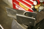 | December 1, 2009 - Panhard rod mount!
As I've mentioned, I'm using the Fast Cars suspension as a base for my design - albeit with a bit more adjustability built in. In that case, the Panhard bar mount is in front of the axle. This means it has to be fairly tall, and it has some support braces to keep it from flexing under side loads. The roll center of the rear axle is the center of the Panhard bar, and the usual geometry means the bar should be in line with the center of the axle at ride height. Thus the long bracket design.
I've decided to put mine behind the axle. This lets me use a straight bar instead of having a bend to clear the nose of the differential. It also means I can take advantage of the contours of the body and use a much shorter mount. It's also a bit of an odd shape and will have a very solid connection to the body of the car. It's made of 2x3 tube instead of the 2x2 in the Fast Car setup and the extra width is in the right place to resist lateral loads. It should be significantly stronger but there's not much clearance for the bar. I think I'll be able to pull it off though.
I should have this welded in to place shortly, I just have to pull out a bit of carpeting inside the car so nothing catches on fire. You know, the usual.
While underneath working this out, I think I figured out how to mount a sway bar to the rear. Hmm.
entry 220 - tags: rear axle, panhard, suspension | | | 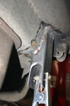 | December 2, 2009 - The Panhard bar mount welded in place.
This is one solid sucker, I'm very happy about that. The bend in the body makes it good and strong.
entry 221 - tags: panhard, rear axle, suspension | | | 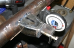 | December 2, 2009 - With the body mount in place, it's time to build the one on the axle.
I welded one of the threaded bungs into a length of 1" pipe and attached it to the body. Then the axle got put into place and I measured the distance from the bar to the axle. That gave me what I needed to figure out what the mount on the axle should look like.
I went through a number of possible designs for this. The final one - shown - has a bracket made of a section of 2x2 bar with a nice thick wall. It's welded to a support made of 2x3 bar, reshaped to meet up. There's a nut welded on the back side of the bracket. A lot of designs I see in circle track catalogs put the bolt in single shear instead of double like this, but I prefer this design.
entry 222 - tags: rear axle, panhard, suspension | | | 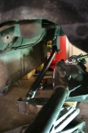 | December 2, 2009 - And voila!
The rear suspension linkages are all in place. The axle is sitting quite a bit lower than usual to show off the bar. In case you're wondering what a Panhard bar does, it provides the lateral support for the axle.
The two outer (lower) trailing arms keep the axle straight in the frame and transfer the brunt of the power to the chassis. The center link at the top of the diff keeps the whole thing from rotating under power and lets me set the pinion angle. And the Panhard bar transfers the side loads into the frame. With this whole lot in place, the axle can twist up and down to let the wheels follow the road, but it will always stay properly aligned to the chassis. Cool.
It's not completely finished, of course. I tucked that Panhard bar into a pretty tight spot, and it only clears the back of the axle by a millimeter or so. More importantly, the bracket on the axle hits the body of the car. A bit of reshaping will solve that problem, of course, but I think I'll have to pull the fuel tank to do it properly. No worries, that looks like a pretty straightforward job.
entry 223 - tags: panhard, suspension, rear axle | | | 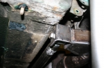 | December 2, 2009 - Here's the interference between the body and the Panhard bar mount.
It's not dramatic, there's only about an inch of up travel left anyhow. It'll be simple to add the space I need without any real consequences anywhere else.
At the top of the picture is the bracket that originally held the straps for travel limitation. I'm thinking it'll be a good place to put a sway bar end link.
entry 225 - tags: rear axle, suspension, panhard | | | 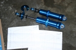 | December 16, 2009 - The shocks are here.
They're a set of custom single-adjustable T2s from AFCO. I worked with AFCO on the suspension for the Targa Miata and I was really happy with the process. Not just the final result, but the experience of working with the company. They're very responsive and willing to do all sorts of oddball things.
The custom shocks weren't that expensive, either. In fact, I probably would have spent more by going with a non-adjustable off-the-shelf coilover setup from someone else like QA1. I have a good collection of springs from previous projects, so I should be able to use those to get into the right ballpark. Most shocks in this price range have a fixed valving, which won't let me experiment with the suspension to get the ride and handling sorted out. Since I really don't have a clue what sort of rates I'll be running - particularly in the rear - I need the ability to swap springs around. The T2 has a huge adjustment range, so I won't have to get them revalved if I swap springs. I went with a single adjustment (rebound) as that's the more important one. If I want to upgrade them to a double-adjustable setup, that's a fairly easy change to make.
The shocks in the picture are for the rear. They've got a 5" stroke for some decent suspension travel back there. The upper perch comes off in seconds without tools, making it very easy to swap springs. The rubber bumper on the shock shaft isn't intended as a bumpstop, as I'll be using the factory MG one attached to the frame. The rubber's just there to protect the shaft seal in case of problems. The shocks are rebuildable if necessary. Oh, and the aluminum body is light, not that this is a big factor with a big heavy live axle.
Overkill? I don't think so. I like my cars to handle. The MG isn't just going to be a straight-line car. I picture it as a great touring car that just happens to have the ability to rip up a series of corners without breaking a sweat.
entry 227 - tags: suspension, shocks | | | 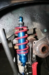 | December 16, 2009 - After a bit of cogitating, I built this lower shock mount for the rear axle.
I'm not completely happy with it, it's not as elegant as I'd like. But it should be strong enough. It's 1/4" plate, welded to the lower trailing arm bracket as well as to the axle tube. There's a triangular reinforcement taking care of some fore-aft strength. I'm still redesigning it in my head, we'll see. That lower shock mounting point carries the entire load of the car (well, 1/4 of it). Assuming the car is around 2600 lbs and evenly balanced (possibly both fairly big assumptions), that means there's 650 lbs on that perch. If it's designed for a 3g load, that means it has to support approximately 2000 lbs. I'll definitely be monitoring this!
The upper mounts will be attached to a plate that will spread the load somewhat. At least, that's my plan. We'll see how that works out.
Underneath the bumpstop, you'll see part of the original MG axle sitting on top of my axle tube. This means I'll have the same bump travel as the original suspension. I'm estimating a bit here, trying to set the shock up so it doesn't quite bottom out at full compression. I expect to have to do some fine-tuning in this area.
entry 228 - tags: rear axle, suspension | | | 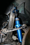 | December 16, 2009 - The front shock mounting is much easier to figure out.
The shock is basically the same design we worked out for the Miata application, but fitted with a different upper mount. The bottom bolts right in to the Miata control arm, and a simple bracket will take care of the top. Lots of clearance. I left that upright on the frame for this purpose, looks like I got the dimensions just about perfect. It'll be tied into the unibody and hopefully cross-braced across the engine bay once I know how much room is available to me.
entry 229 - tags: suspension, front suspension | | | December 17, 2009 - Every shock from AFCO comes with a dyno chart.
And not just a representative dyno chart, but one for that actual shock with the serial number on it. I had some questions about the dyno curves on my rear shocks so I sent an email off to my contact at AFCO. He printed out the charts for my particular shocks, checked them with a technician and replied back with details on what I was seeing.
Now that is why I like to work with them!
entry 231 - tags: suspension | | | 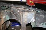 | January 7, 2010 - More sheetmetal work today.
I continued to reinforce the shock towers (for lack of a better term), tying them firmly into the chassis. The existing sheetmetal is welded to the outside edge of the upright tube, and the plates tie it in on the inside. I think it'll be strong enough, although I'm still going to put a few bars running across and back to the firewall, depending on fitment. There's also one piece missing that will be added as soon as I know exactly what's going on with the exhaust routing.
I also attached the upper shock mounting points for the front, so I now have a complete front suspension. When the passenger's side shock tower looks like this, I'll basically be done with the front.
entry 247 - tags: sheetmetal, suspension | | | 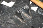 | January 10, 2010 - It was a day of fabrication.
I spent the whole day cutting weird shapes out of cardboard, duplicating them in steel and then welding them in. The stock inner fender sheetmetal is fairly thin, so it takes a certain amount of finesse not to burn through it.
I finished up the shock tower on the passenger's side, and I'm happier with how this side came out. I was smart enough to tie the inner metal directly to the upright first, then add the new braces. I have some work ahead of me inside the wheel well on the driver's side. Still, the front end is obviously much more solid now and I'm pretty much done with it for a while.
The guy in the picture is an upper shock mount for the rear. I went through a couple of designs for this, and this is the final version. The plate will be welded inside the wheel well and will help spread the load somewhat. The spacers on the inside of the mounting tabs help keep the tabs clear of the adjuster on the shock, allowing me to put a wider base on the tabs than I would otherwise.
entry 250 - tags: suspension | | | 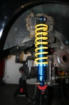 | January 11, 2010 - A rear shock in place!
Very exciting. The place where I mounted the plate for the upper shock mount is well tied into the structure of the car and is very solid - although there is some carpet just on the other side at one point, which I got a little warmer than the designer intended. The mount on the axle is only tacked in place, but that's an easy thing to change. I have to pull the rear end out to put a lower mount on the driver's side.
The upper mount is positioned so the shock is almost bottomed out when the stock bumpstop - visible above the axle in this shot - is compressed and the other wheel is at full droop. Worst-case scenario, of course. But there's a problem. When I assembled everything, I discovered that I only had about an inch of droop travel at my expected normal ride height. I've been spending so much effort on making sure I have lots of compression travel, and with my 5" long shock travel I assumed I'd have good droop. Nope.
Maybe my worst-case scenario was a little too worst-case. I'll have to do quite a bit of surgery to the stock wheel well to make that happen. Heck, I knew that already. Still, I do have an option. AFCO sells a replacement upper rod end that's an inch longer than the ones I have. This would cut an inch of my compression travel (would it be missed?) and give me another inch of droop. We'll see how things work when the car hits the road. For the time being, I'm just happy that I have suspension on three corners now!
entry 251 - tags: suspension | | | January 15, 2010 - A long day with not much actual progress.
I managed to cut out a bracket. Oooo!
Actually, I did quite a bit more than that, mostly planning. I was following a pickup this morning and noticed that the shocks were mounted very far inboard. I realized that this would give more wheel travel for a given amount shock travel, and that I had previously considered a slightly more inboard mounting point on the MG. Obviously I wouldn't want to go too far, as my coilover setup would put some pretty major bending loads on the rear end and the lessened shock travel would mean less precise damping. But would it make much of a difference?
So I dragged the rear end back off the workbench were it was set up to have the shock bracket mounted on the driver's side, and stuck it back under the car. A bit of rough measuring showed that my alternate setup would give me an extra 1/4" to 3/8" of droop. Nothing to be ashamed of for such a simple change, and it would also give me more room in the wheel wells. It would also drop the lower mounting point of the shock down considerably, about 1.5" closer to the ground.
However, while doing my measuring, I discovered I'd mis-measured last time and I really had 2" of droop travel from my expected ride height. I suspect I hadn't let the shock fully extend, these AFCO shocks don't have internal pressurization so you have to actually pull them open. If the damping is cranked up, that takes a significant amount of effort. Regardless of the cause, it appears I have nothing to worry about so I'll continue as planned. The rear end came back out and was reinstalled on the workbench.
While poking around back there, I started looking at other packaging concerns - specifically, the available space for a muffler. There isn't much. The layout of the MGB GT's truck is a little weird, though. There's a fairly tall flat floor. If you lift it up, you discover a cavernous hole that exists to house the spare tire and quite possibly enough tools to disassemble the car. If I move the fuel tank into this space, that opens up a huge amount of room for a muffler underneath. I could either move the existing tank without too much trouble or build my own new one with some baffling inside. Mounting the filler is going to be a bit more of a problem as it would then be about level with the tank, but I have an idea.
More work!
entry 253 - tags: packaging, suspension, fuel tank | | |  | January 17, 2010 - Touchdown!
A bit of time cutting and welding, and suddenly I had full suspension on all four corners. Naturally, the only thing to do was to bolt on some wheels and drop the car to the ground. The spring rates (250 rear and 375 front) were chosen simply because they were handy, and the ride height was set to "no preload on the springs". It actually turned out pretty well after I dropped the nose down slightly!
When I tell someone about having the car sitting on its wheels, they don't seem to share my excitement. This car has a completely new suspension, not just a bolt-on setup! This is a huge step!
After having the car up in the air for so long, it looks much smaller sitting on the ground. Janel thought it looked like a Hot Wheels car with the wheels poking out of the wells.
Turns out my initial measurements for droop travel were accurate - there isn't much. I think the smart way to fix that would be to simply move the lower suspension mounting point up by an inch or so. Of course, I had the car a little tall today because I can't compress the rear suspension much without cutting the rear fenders. That'll happen soon enough, but I'll probably concentrate on the other big jobs first.
Less than an hour after touchdown, the car was in the air again. And I was dragging the engine hoist towards the car...
entry 255 - tags: suspension | | | 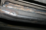 | August 12, 2010 - While I was playing with the welder, I decided to take one more shot at welding the new rear frame rail to the bottom of the car.
Previously, I'd found it almost impossible to weld the two together without burning through the floor. So the rail was attached with rosette welds through the top. But it just looked wrong when you peeked underneath.
With a different technique, I was able to make this happen. I'm much happier with that.
entry 362 - tags: frame rails, suspension | | | 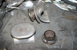 | November 1, 2010 - I didn't feel much like working on the car tonight, but I figured I'd wander into the shop and just do one thing.
Like bolt up that lower control arm that was next on the list before I had to stop yesterday. Arm bolted up, mission accomplished. Then I decided to trace out the cut line for that fender. And then I decided to pop the stainless steel trim off the side of the car to get an idea of how hard it would be (answer: easy). Then I saw the bumpstop targets on the workbench and decided to work on them for a bit.
This is how stuff gets done. By accident!
The bumpstop "targets" are the flat plates on the rear axle that the bumpstop bangs into. I took them off the MG axle. I'm sure they have a better name. Anyhow, I know I need to raise them up a bit for the new suspension. The AFCO shocks can damage their seals if they're allowed to bottom out, so I need to make sure I get this right. But unfortunately I can't tell exactly how much those bumpstops will compress. So the solution is to make them adjustable.
First, I welded a nut to the bottom, underneath the hole that MG thoughtfully left here for this purpose. This gives me the ability to bolt on spacers of various thicknesses. I'm going to start with a 1" pedestal. That's a bit conservative, but I can use a travel indicator to tell how close I'm getting to full shock compression and adjust from there.
entry 419 - tags: suspension, rear axle | | | 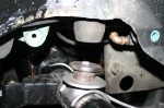 | November 1, 2010 - Here's an image of how the bumpstop target sits on the axle.
The middle of the bumpstop is nicely hollow to allow for the bolt head to fit inside. Notice how clean the 39-year-old bumpstop target is? The bead blaster strikes again!
entry 420 - tags: rear axle, suspension | | | 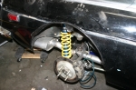 | November 7, 2010 - With the brakes all plumbed in, it's time to bleed them.
Unfortunately, I still have a mismatch of front brake pads (1994 Miata), brake rotors (1994 Miata) and caliper brackets (1990 Miata, which uses smaller brakes). I have a set of the later brackets on the way, but with Janel available to help me bleed I wanted to do something. Well, the Seven was just sitting there with an engine problem awaiting my attentions, and it uses the 1990 size brakes. So I grabbed the rotors and pads from that car and voila! Front brakes.
I've also cut the rear arches away to clear the tires on full bump. There's a double skin to the body here so some black duct tape was used to seal it up until I weld in an insert to join the gap. It was gratifying to see how clean the metal inside that cut section is. That's a rust spot for the cars, and mine was pristine inside. Was.
Time to bleed the brakes! All the suspension pivots have been torqued up and the springs are in place. Does it seem as if I'm working towards something here? Perhaps.
entry 427 - tags: brakes, suspension, body, fenders | | |  | November 7, 2010 - The brakes proved problematic to bleed.
I think I have one bad flare which will have to be sorted out, and it took forever to get the rears working. But I got them to the point where they'd stop the car, so it was time.
I bolted on the wheels, checked tire pressures, attached the hood and dropped the car to the floor. It's always fun how much smaller they get when they're sitting on their feet. This car's been on jackstands in the garage for a long, long time. The springs are 8" 375 lb in the front and 10" 250 in the rear, mostly because that's what I have. I snugged the spring perches up to the springs at full droop and nailed the ride height almost perfectly.
After a lot of shuffling around and shoving of bits and pieces into handy corners, I was able to free the MG and point it towards freedom.
entry 428 - tags: first drive, brakes, suspension, springs | | | 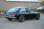 | November 15, 2010 - With the video of the first drive getting attention, I'm fielding a few questions about the car.
The most common is about the wide track and the suspension choices, typically with people pointing out that I could have used a bolt-in setup from Fast Cars. I did actually use a rear end similar to their design. But here's a recap of the thinking, all gathered together in one place. This is taken from an email I sent to someone.
About the BGT's suspension - I decided to go with Miata suspension on
the car, in large part because it's a setup I understand very well
given my history. I also have a large collection of spare parts, and
this makes it much easier to keep a fleet of cars happy. Being able to
swap brakes between the Lotus replica and the MG came in handy just
last week as I borrowed some parts off the Lotus to get the MG
driveable. It's also much less expensive than buying one of the
coilover setups on the market for the B, and allowed me to toss the
stock subframe and other bits. As an unplanned side effect, I also
saved quite a bit of weight.
So, going with the Miata front suspension meant I had a wider front
track. I could have narrowed it, but then I would have messed up those
beautifully controlled roll centers that I think are a major
contribution to the Miata's handling.
Now I needed a wider rear track to match. I seriously considered going
with a Miata rear end, which is a nicely packaged independent. I've
seen photos of a BGT with this rear end installed, but there were a
couple of problems. The first is the amount of sheer destruction
required to the rear of the car to make it fit. Secondly, the rear end
wasn't strong enough to deal with the assault from the V8, so I would
have had to modify it for a different differential. That's not a major
problem but it was an additional expense. By mixing the appropriate GM
parts, I was able to use the differential from the Camaro and a
standard-length axle housing to make the best use of what I had. If
the live rear doesn't work out, I'll change it over to a Miata rear
eventually, but I'm pretty happy with the overall engineering of what
I have. The car is stronger for it.
entry 451 - tags: suspension | | | 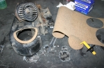 | November 26, 2010 - You'd think I had plans to spend more time driving this thing.
In order to keep Janel happy, the car needs a heater. So I found the wiring for the heater fan switch (someone had helpfully placed a label on it that said "HEATER FAN"), plugged it in and...nothing.
Nuts.
So I stuck the switch in the bead blaster just to make sure there were no corrosion problems. Checked the power at the fan and it was getting juice and a good ground. Just for fun, I grabbed the fan out of the parts car and plugged it in.
Success.
The car had a bad heater fan. Luckily, it's possible to remove the fan without affecting anything else and there's just enough room, so I swapped them out. There was a fair bit of noise going on though. I decided I needed to move the fan outwards very slightly and give it some noise isolation, so I made a gasket out of cork. Mission accomplished, the car now blows air through the heater into the interior. I also taped up the cold air inlets that are not currently attached to anything to minimize the amount of cold air intrusion into the cab.
Speaking of gaskets, I slipped a thick composite gasket between the passenger side header and the head. That will hopefully cut down some of the noise from an exhaust leak - although I also realized that there's still a significant hole in the passenger's footwell that's used for the wiring. I have a grommet to go there but I'm still working on the wiring, so it'll stay open for now.
Just because this wasn't enough, I raised the ride height a bit to get closer to my target height. The fender cutouts make it look a bit odd but that's a temporary thing. This may improve the ride and handling as well, although the visible different camber on each front wheel will probably have some effect.
The car should be ready for more driving tomorrow. This is going to be fun.
entry 480 - tags: exhaust, suspension, HVAC | | | November 27, 2010 - Spent some more time driving today.
The loud exhaust drone at 1500 rpm seems to be gone, that's probably due to the exhaust tips. Excellent. It's still not a quiet car, I'm going to work a bit more with the sound insulation and see what I can do there. A lot of the noise seems to be coming through the firewall. There's still some carpet to install, maybe it'll help some.
The ride is also better with the slightly raised height. I'll spend some time tweaking the shock settings, but I suspect it's going to want a bit less rear spring. It has some 250 lb ones now, and I think the lightest I have in the garage is 225. I'll give those a try.
The heater works well. Good.
Janel was driving this time as I monitored the car through an OBD-II scanner. Can't do that with most MGs! Anyhow, she seemed a bit taken aback at the sheer number of creaks, squeaks and bangs from the car as it first started moving down the road. But once she got into the gas, she started laughing. Especially when I reported she hadn't even hit 50% throttle. She likes the car a lot.
Not over-fond of the brakes, as they don't bite too aggressively. The power booster isn't over-boosted and I'm not completely sure the R4S pads are fully bedded. They're also going to be a bit slippery in the near-freezing temperatures we used on the test drive. I am tempted to replace them with a set of Performance Friction PFC 97 pads, which is what I use on the Targa Miata race car. I'll give the R4S a bit more time, as they're usually a good setup.
entry 481 - tags: brakes, test, suspension, exhaust | | | November 28, 2010 - I changed out the rear springs to 225s earlier and took the car for a bit of a drive.
Good, although they're 8" long and don't have quite enough travel for my 5" rear shock travel. It's possible they could coil bind on a really hard hit. I'll keep them in for a bit of testing first, and if they get the nod I'll pick up some 10" ones.
I just swapped out the front springs from 375 to 300, because that's what I have in the garage! I'll drive the car tomorrow (weather permitting) and see how they feel.
I have to say, changing springs on this car is ridiculously easy. It only took 5 minutes to change both front springs. All I have to do is lift the car, pull the wheel, remove the external shock boot (attached by velcro), spin the perch down, unclip the upper perch, unbolt the top of the shock, pull the old spring off, drop the new one in and just reassemble. It sounds like a lot of steps when laid out like that, but it's very fast. No need for a spring compressor and only one bolt.
entry 487 - tags: suspension, springs | | | 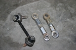 | January 18, 2011 - The sway bar has an upward angle to it due to the bar placement.
The stock end link - the black one - made this as bad as it could be. So I decided to go with a shorter unit. I have boxes full of old Miata suspension pieces, of course, and the heim-jointed end link in the middle is from the "end link" box. Seriously, I have a box for Miata end links. I also have a box for bumpstops, a wall full of springs, a cord of sway bars, random steering column parts, etc. And at least three boxes of wires. But I digress.
The unmodified heim-jointed link was still too long. So I cut it down, as you can see on the right. There's still a lot of thread engagement so strength is not a problem, but I've made the angle of the bar much better.
It's not the only suspension work I did today. When I was first doing the suspension work on the car, I didn't pay too much attention to the control arms and suspension uprights I used. All the important dimensions are the same. But in my fevered excitement to assemble the car for the First Drive, I left those parts on the car. And that was a problem.
Mazda tweaked the Miata's suspension in 1999. The control arms got beefed up a bit, although the dimensions were basically unchanged. The one change was on the taper of the upper ball joint. The steering knuckle/upright was also very similar, with the steering arm moved up by 7mm and the appropriate taper on the seat for the upper ball joint.
Well, when I looked at what was on the car, I realized that I had the new design upper control arm on one side, but the older steering knuckle. On the other, I had the older parts. This is less than ideal, so I swapped everything out for the newer designs. It was actually a pretty quick job, the guy who built this car was careful to leave enough room to do things like remove suspension bolts. Whew!
entry 537 - tags: suspension, sway bar, end links | | | 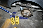 | January 23, 2011 - During construction, Janel often referred to the MG as her little grocery getter.
And you know what? We're actually using it for grocery runs. She's pretty happy with how it's evolving, between the better/more compliant tires and the sway bar it feels much better planted and less skittish. She also really likes the current suspension compliance.
I've known since I put them on that the current springs weren't long enough - they coil bind before full compression. And I suspect that's actually happening once in a while. So I swapped in a set of 10" springs with a 250 lb rate instead of the 8" 225s that were in there. Why the rate change? Because that's what I have! I'll see what change this makes to the dynamics, and then order some springs of the appropriate rate and length. I've said this before, but it's so easy to change the springs on this car!
entry 540 - tags: suspension | | | June 21, 2011 - It's been a gratifying day.
I posted pictures of the car to the various forums that have been interested in it over the years(!), and the response has been very good for the ego. Actually, even I'm finding the end result stunning. I've had it in my head for a couple of years now and here it is in the metal, and it works better than I expected. Some of it is the details - the way the clear front lights, deleted overriders and air dam beef up the front to match the flares, for example. Some of it is just the way the body flows in a way it never has before. I've spent a lot of time just running my hand over the car.
I also drove it to work. Of course. And as a result, when I got home, I changed out all four springs to a stiffer setup (375/300), bumped up the damping and realigned one of the exhaust pipes to keep it from leaning on the body. You know, the usual post-drive changes. I think what the car really needs is some roll stiffness, though. I'll put on a rear sway bar and beef up the front one later this week and see what that does.
entry 596 - tags: ego, body, suspension | | |  | July 13, 2011 - Naturally, the first thing I did after the cruise night was put the car up on jackstands.
I wanted to see if I could fit a rear sway bar. Then I decided to look for the point where the exhaust was touching the body. And while I was at it, I gave the whole car a good look-over.
Good thing, too. This is the passenger's side upper shock mount. This has to support the entire weight of that corner of the car, and it's been gradually twisting. It's possible that my springs were going into coil bind, but a telltale I'd put on one of the coils says no. However, I did have a set of 8" 225 lb springs on the car for a while, which would have had potential for coil bind. I suspect that's what happened here. Interestingly, the other side doesn't have any problem - and I welded along the top edge of that one, but not this one.
There is a design problem with my mount when I look at it. It doesn't have any reinforcement above the shock mounting point, which is right where it needs it the most. And that gave me my solution. I welded up the crack and added a brace that runs upwards from the shock bolt to another plate welded to the wheel well. I think it'll make all the difference. Naturally, I forgot to take a picture when I was done. I didn't do the driver's side today, I'll get it later.
It's inevitable that things like this will show up. This is a pretty heavily re-engineered car. That's why I like to poke around under the car once in a while to see how things are working.
While I had the shocks off to fix this, I changed the 300 lb springs for my 10" long 250s again. Yes, they've been on the car before. In fact, I think the current spring setup (375/250) is what I originally installed when I built it!
entry 628 - tags: suspension, damage | | | 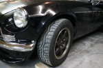 | July 13, 2011 - So how did the new spring setup work?
Beautifully. I'm not sure what's changed from the first time I had this combo on the car, but the car has a beautiful fluidity over bumps and a well-controlled ride. It's as if I've discovered some secret suppleness setup. It's not perfect yet - the car is a bit disconcerting on turn-in. It's almost as if the rear takes a moment to catch up to the front. I think part of the problem is very responsive steering and too much power assist. If the steering had a bit more heft to it, it would be more in line with the way the rest of the car works. This is something that's been on my to-do list for a while. Soon!
I also beefed up the front sway bar while I was working on things. Since I can't figure out how to package my rear sway yet, I figured I'd let the front do the work. That seems to have worked out nicely.
I also changed rubber. The RA1s that were on there were really just temporary, but they helped the car stick to the road. But I'd picked up a set of Azenis RT615s a while back for a killer price, and they were just sitting in the garage. I'm not a huge fan of the Azenis as I find they heat-cycle too quickly and have a very stiff sidewall. But that's based on my experience with the original RT215, and I had these just sitting around. They certainly look better than the well-worn Toyos and the 10mm narrower width means they fit the flares perfectly. Is this where the change came from? No matter, I'm a happy camper right now.
entry 630 - tags: tires, suspension | | |
|

 THE DIARY
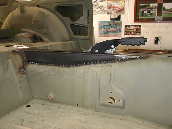
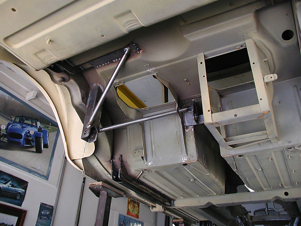