| THE MG |
|
|
 | | 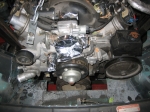 | December 31, 2009 - Here's why I knew I needed to fit the real engine instead of just my plastic one.
The pulleys and water lines and accessories make things more complex. And it became apparent pretty quickly that I needed to open up the front of the engine bay a bit more. Time to chop a bit more off the car!
entry 241 - tags: engine, destruction, first fitment | | | 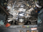 | December 31, 2009 - Voila!
A minute with Mr. Sawzall and the offending parts are removed. I have some structure to put back in to ensure the bumpers don't fall off the car, but the engine slipped in to place.
I also had to open up the hole in the interior for the shifter. It's in the perfect place, but the Hurst shifter on our T56 is a bit larger in diameter than the hole.
entry 242 - tags: engine, destruction, first fitment | | | 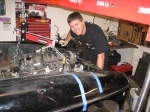 | December 31, 2009 - Janel felt there should be a picture of yours truly in the build diary.
Hi Mom!
entry 243 - tags: Keith | | | 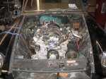 | December 31, 2009 - And voila!
The engine is installed. Not for the final time, as I'm going to have to pull it to finish welding up the frame and some other bits. There's also a cross piece in the transmission tunnel that wants to be just a little bit smaller - I've cut it once, but not quite enough. That will let the whole drivetrain level out.
It's a tight fit in spots. The distance between the oil pan and the steering rack is minuscule. The transmission tunnel is shrink-wrapped around the trans. And I'm really not sure how to fit the exhaust - even coming out the fender wells is going to be tight, I'll have to make sure there's enough clearance for the tires. The oil filler looks like it's making a bit of contact with one of the stiffening ribs in the hood. But these problems can be overcome!
But there it is - a complete LS1/T56 in a 1972 MGB.
entry 244 - tags: fitment, first fitment, engine, transmission, destruction | | | 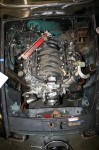 | January 1, 2010 - I spent a bunch of time today simply crawling around the car, figuring out what needs to be done.
The short version: lots.
By doing a bit of reworking to the heater box above the transmission tunnel, I think I can pull the drivetrain back by another .75". That will give me a bit more room on the steering crossmember and move the shift lever back to the back of the factory hole instead of in the center. I can deal with where the engine is now but I'd prefer just a little bit more room at the front.
While the engine is out so I can cut the heater box, I'll fully weld and reinforce the front frame so it can deal with the load of the engine. That's going to be a bit of a tough call, but I think I can do it.
This is a very tight fit overall. The exhaust routing will definitely be through the fender wells, and I'll have to make sure it doesn't interfere with the tires. The accessories all fit nicely, that's a bonus. I'm trying to figure out how large a radiator I can stuff in here, and how the fans will fit. Brake hydraulics will be a big challenge if I want to keep power assist.
So much to do.
entry 245 - tags: fitment, first fitment, space | | | 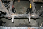 | January 3, 2010 - I pulled the engine out again so I could chase down the fitment problems.
Step one was to reinforce the front end and finish up the welding. Previously, the steering crossmember was only tacked into place and the clearance cuts were unfinished. So I filled them in, added some diagonal braces/fillets and finished the welding. I also closed off the front of the frame rails.
Not visible in the picture is the beginning of the connection between the vertical suspension member and the unibody. The driver's side is partially done. I've also spent some time figuring out the design up the upper shock mounting tabs, as I need to make sure they're in place when I finish the bracing.
entry 246 - tags: frame | | | 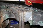 | January 7, 2010 - More sheetmetal work today.
I continued to reinforce the shock towers (for lack of a better term), tying them firmly into the chassis. The existing sheetmetal is welded to the outside edge of the upright tube, and the plates tie it in on the inside. I think it'll be strong enough, although I'm still going to put a few bars running across and back to the firewall, depending on fitment. There's also one piece missing that will be added as soon as I know exactly what's going on with the exhaust routing.
I also attached the upper shock mounting points for the front, so I now have a complete front suspension. When the passenger's side shock tower looks like this, I'll basically be done with the front.
entry 247 - tags: sheetmetal, suspension | | | 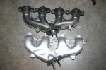 | January 7, 2010 - The exhaust manifolds that came off the Camaro were odd - they were made out of a couple of pieces of stamped steel welded together.
They also put the exhaust on the passenger's side right into the footwell. Not cool.
Just for fun, I brought these guys home. They're the manifolds that come off the LS3 crate engines we use at Flyin' Miata. I'm not sure exactly what they're originally for, but they're pretty nice looking. The driver's side (bottom in the picture) has a dent to clear the steering column, and the passenger's side runs downwards instead of back. If I can use them, it'll save me a huge amount of work.
entry 248 - tags: exhaust | | | January 7, 2010 - Dumb.
Remember my trip to the junkyard to pick up some Rabbit fenders so I could scavenge the arches? At the time, I thought the rears might actually work pretty well but the yard wanted a pile of money for them.
Well, it turns out you can get patch panels to repair Rabbits. New front fenders are available from JC Whitney and others, but even better Rabbitparts.com carries a rear arch repair panel that's exactly what I need. They're only $48 each and brand new steel. I'm going to pick up a pair to see how they work, and I may end up ordering another pair to replace what I have if the shape looks a bit better.
Yeesh. Never thought to check before.
entry 249 - tags: body | | | 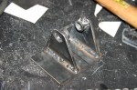 | January 10, 2010 - It was a day of fabrication.
I spent the whole day cutting weird shapes out of cardboard, duplicating them in steel and then welding them in. The stock inner fender sheetmetal is fairly thin, so it takes a certain amount of finesse not to burn through it.
I finished up the shock tower on the passenger's side, and I'm happier with how this side came out. I was smart enough to tie the inner metal directly to the upright first, then add the new braces. I have some work ahead of me inside the wheel well on the driver's side. Still, the front end is obviously much more solid now and I'm pretty much done with it for a while.
The guy in the picture is an upper shock mount for the rear. I went through a couple of designs for this, and this is the final version. The plate will be welded inside the wheel well and will help spread the load somewhat. The spacers on the inside of the mounting tabs help keep the tabs clear of the adjuster on the shock, allowing me to put a wider base on the tabs than I would otherwise.
entry 250 - tags: suspension | | | 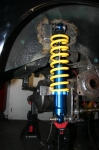 | January 11, 2010 - A rear shock in place!
Very exciting. The place where I mounted the plate for the upper shock mount is well tied into the structure of the car and is very solid - although there is some carpet just on the other side at one point, which I got a little warmer than the designer intended. The mount on the axle is only tacked in place, but that's an easy thing to change. I have to pull the rear end out to put a lower mount on the driver's side.
The upper mount is positioned so the shock is almost bottomed out when the stock bumpstop - visible above the axle in this shot - is compressed and the other wheel is at full droop. Worst-case scenario, of course. But there's a problem. When I assembled everything, I discovered that I only had about an inch of droop travel at my expected normal ride height. I've been spending so much effort on making sure I have lots of compression travel, and with my 5" long shock travel I assumed I'd have good droop. Nope.
Maybe my worst-case scenario was a little too worst-case. I'll have to do quite a bit of surgery to the stock wheel well to make that happen. Heck, I knew that already. Still, I do have an option. AFCO sells a replacement upper rod end that's an inch longer than the ones I have. This would cut an inch of my compression travel (would it be missed?) and give me another inch of droop. We'll see how things work when the car hits the road. For the time being, I'm just happy that I have suspension on three corners now!
entry 251 - tags: suspension | | | January 13, 2010 - Good question.
Someone on the Grassroots Motorsports forum asked about the relative difficulty of building a car like my Seven or the MG. For those who don't want to go read the discussion on the forum (there are some good points from other folks to do with registration and the like), here's what I answered. Note - I don't usually refer to the Seven as a Locost because I didn't build the frame. But that's what it is. Warning, long!
Here's a point-by-point comparison.
The Locost is basically a clean sheet when it comes to packaging, and the frame is built to accommodate whatever powertrain will go inside. Before the first piece of metal is cut, there are no constraints. This can cause a problem for some people, as design paralysis can kick in But it does side-step some problems right from the start.
The MG, on the other hand, is heavily constrained. The new drivetrain has to fit into an existing package. In my case, I'm making dramatic changes to the car to build what I want to build, but I still have to fit everything into the body and deal with things like the pre-determined position of the fuel tank or the steering column. Of course, this also means I don't have to deal with problems like trying to figure out where to place and how to mount the fuel tank. But just think of the exhaust - on a Locost, you stick it out the side of the car. With the MG, it's going to have to go under the car and thread through the suspension.
The Locost is very simple. It's a car, distilled. There's nothing there that isn't required. This makes life easy.
The MG, not so much. It's expected to be a real car with a heater, a certain amount of sound and noise insulation and the like. Of course, most of the hard work has already been done - the windows roll up and down, it's carpeted, it has a heater and ventilation plumbing, etc. Some care is required to retain all this.
The Locost is built out of clean steel. The MG has 40-year-old undercoating. Yuk.
With the Locost, you're responsible for everything. Need fenders mounted to your wheels? Make a bracket. Need seats? Figure 'em out. Need a steering column, a fuel filler, a scuttle, etc - it's all you. You've got some design freedom, but nothing comes for free. You have to solve every single problem involved in designing a car. This is the biggest part of the work.
With the MG, I only have to deal with the parts I'm changing. I don't need to figure out how to hang doors, mount the headlights or deal with airflow management behind the dash. That's been done for me. This helps. Of course, it would have helped more if I hadn't tossed the stock suspension away!
So which is harder? From a problem-solving point of view I'm going to say the MG, due to the existing constraints. For example, I'm not only going to have to figure out a steering column, but I have to figure out how to make it work with the existing firewall and column mounting. But it's a pretty close race, and if I'd decided to do a more traditional 302 or Rover swap into the B - which would have retained the suspension front and rear - then it would have been the other way around. My MG is a pretty extreme makeover. It helps that I have the knowledge that I gained during the Locost build, I suspect, but it's difficult to quantify that as I always assume when looking back that I knew then what I know now.
Time is hard. I didn't build the Locost frame, and I was single then. Instead of building in my own garage living on my own, I'm building in a garage that's attached to the house I share with my wife. This means no late-night grinding and hammering. It also takes me longer to do simple things like make dinner! I'm going to estimate similar time overall.
Money? That's such a variable. I think it's actually going to be pretty close. I could have found a cheaper MG (heck, a free one found me recently that would have been a perfect starting point) but I also bought my Locost frame. I don't pay attention to the total costs, I don't want to know. I just try to do everything for the minimum cost to do it right.
In terms of skills, I'd put them at a wash. I'll have to do more fine bodywork on the MG (no rivets here) due to my need for flares, but overall the basic skillset of shaping and welding metal, wiring, plumbing and painting is the same. Had I found a different MG to start with, I expect rust repair would have been a new skill I'd have to learn. But it's just an application of the metal and body work.
entry 252 | | | January 15, 2010 - A long day with not much actual progress.
I managed to cut out a bracket. Oooo!
Actually, I did quite a bit more than that, mostly planning. I was following a pickup this morning and noticed that the shocks were mounted very far inboard. I realized that this would give more wheel travel for a given amount shock travel, and that I had previously considered a slightly more inboard mounting point on the MG. Obviously I wouldn't want to go too far, as my coilover setup would put some pretty major bending loads on the rear end and the lessened shock travel would mean less precise damping. But would it make much of a difference?
So I dragged the rear end back off the workbench were it was set up to have the shock bracket mounted on the driver's side, and stuck it back under the car. A bit of rough measuring showed that my alternate setup would give me an extra 1/4" to 3/8" of droop. Nothing to be ashamed of for such a simple change, and it would also give me more room in the wheel wells. It would also drop the lower mounting point of the shock down considerably, about 1.5" closer to the ground.
However, while doing my measuring, I discovered I'd mis-measured last time and I really had 2" of droop travel from my expected ride height. I suspect I hadn't let the shock fully extend, these AFCO shocks don't have internal pressurization so you have to actually pull them open. If the damping is cranked up, that takes a significant amount of effort. Regardless of the cause, it appears I have nothing to worry about so I'll continue as planned. The rear end came back out and was reinstalled on the workbench.
While poking around back there, I started looking at other packaging concerns - specifically, the available space for a muffler. There isn't much. The layout of the MGB GT's truck is a little weird, though. There's a fairly tall flat floor. If you lift it up, you discover a cavernous hole that exists to house the spare tire and quite possibly enough tools to disassemble the car. If I move the fuel tank into this space, that opens up a huge amount of room for a muffler underneath. I could either move the existing tank without too much trouble or build my own new one with some baffling inside. Mounting the filler is going to be a bit more of a problem as it would then be about level with the tank, but I have an idea.
More work!
entry 253 - tags: packaging, suspension, fuel tank | | | 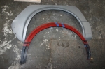 | January 17, 2010 - The new fender flares have arrived.
They're going to be much, much easier to work with than the originals. It's interesting to see just how similar the shapes are front and rear though.
entry 254 - tags: fenders, body | | | 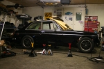 | January 17, 2010 - Touchdown!
A bit of time cutting and welding, and suddenly I had full suspension on all four corners. Naturally, the only thing to do was to bolt on some wheels and drop the car to the ground. The spring rates (250 rear and 375 front) were chosen simply because they were handy, and the ride height was set to "no preload on the springs". It actually turned out pretty well after I dropped the nose down slightly!
When I tell someone about having the car sitting on its wheels, they don't seem to share my excitement. This car has a completely new suspension, not just a bolt-on setup! This is a huge step!
After having the car up in the air for so long, it looks much smaller sitting on the ground. Janel thought it looked like a Hot Wheels car with the wheels poking out of the wells.
Turns out my initial measurements for droop travel were accurate - there isn't much. I think the smart way to fix that would be to simply move the lower suspension mounting point up by an inch or so. Of course, I had the car a little tall today because I can't compress the rear suspension much without cutting the rear fenders. That'll happen soon enough, but I'll probably concentrate on the other big jobs first.
Less than an hour after touchdown, the car was in the air again. And I was dragging the engine hoist towards the car...
entry 255 - tags: suspension | | | January 20, 2010 - With the engine back in the car, I determined the final location of the big heavy parts.
In short - quite far back and nicely placed vertically. I'll have just over 5" of air under the sump at my expected ride height, but the hood closes all the way. The shifter is in just about exactly the stock location.
So the next thing to do was to build motor mounts. The passenger's side was straightforward enough, but the driver's side was a real challenge. The mount is extremely close to the steering column, enough that I'm going to have to weld the lowest universal joint to the shaft instead of bolting it on, as there isn't enough room for the bolt to clear the mount. I finally figured out how to put a motor mount bracket in there, but I don't think I can create the lower section until the engine is out.
I did check the clearance on those new headers I brought home. Nope, they won't fit. The passenger's side is good, but the driver's side is not. That steering column again. The headers are obviously from a car that is several inches wider than our little beastie. I can see the possibility of headers that require the removal of the steering column to install - I'll try to avoid that.
The transmission support will take the shape of a new crossmember - pictures to come. I need to make this removable so I can actually take the engine out of the car again, which made everything much more difficult. I'm almost there. This is a very satisfying stage of the build.
entry 256 - tags: motor mounts, packaging | | | 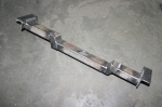 | January 20, 2010 - The transmission crossmember is finished.
Finally! It's upside down in the picture, in the car it steps up to reach the stock LS1 transmission mount. The bits on the end bolt in to captive nuts installed on the frame rails. Of course, I didn't have that set up ahead of time so I first had to weld the nuts on to a piece of 1x2" strap, cut two large 0.875" holes in each frame rail and then weld the strap on to the rails. The holes in the strap and the bracket are perfectly matched to the bolt size so there's no slop at all, which made positioning very important. I put the bolts in shear instead of tension for the simple reason that if they start to back off, my transmission won't start to sag downwards and eventually fall down.
The stud on the rubber bushing on the transmission is an inch long, which isn't long enough to protrude all the way through my mount. Thus the large hole in the middle, which is where the nut for the stud goes through along with a socket to tighten it up. Works like a charm, although I really need to deburr that hole to make it look better in pictures like this.
The raised middle section didn't end up being raised quite enough - the original measurements told me 0.75", and it looks as if 1.25" would have been more accurate after I decided the tail of the transmission needed to be slightly higher. Oh well, it's a good solid fit and it works well. Due to the close tolerances on the holes, it's actually a bit tough to install as the bolts won't thread into the holes unless the mount is perfectly positioned, but I'm willing to accept that particular tradeoff for a precise fit.
entry 257 - tags: transmission | | | 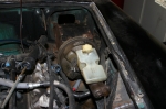 | January 22, 2010 - It's time to make sure I have room for some real brakes.
The car originally came with unboosted brakes, and long-time readers will remember that I rebuilt the master cylinder. That was back when I thought I'd be driving the car as a four-cylinder for a while. Ah, those were the days.
Purists, of course, claim the unassisted brakes are superior in almost every way. But those who are sensitive to subtle hints may have noticed that I'm not much of a purist. I have several cars with unassisted brakes (interestingly, they're all British or replicas thereof) but this car will have a fairly intense power/weight ratio, and I want power assist. Besides, the whole braking system has been replaced with Miata parts, and my rear discs take more pressure to operate than the previous drums.
The problem is twofold - first, there's not much room for a booster underhood. And secondly, the original pedals put the masters above the driver's feet - so there's simply no room for a booster at all in that setup. There are such things as remote boosters which are intriguing. A number of newer vans (and other packaging-challenged cars) also use a "hydroboost", which steals hydraulic pressure from the power steering pump for assist.
But there's an easier way. In 1974 or 75, MG added power assist to the MGB. And in order to do so, they used a very small brake booster, a master cylinder with an angled top to clear the hood, and a different pedal box that put the brake hydraulics in front of the pedal. And it's a simple bolt-in to the earlier cars - although most MG owners go the other way, installing the unassisted setup. I found a complete pedal box, booster and master on the MG Experience website and had it in my hands a week later.
The first trial installation showed that it's a perfect fit. The front outlet is fairly close to my shock tower mount, but a well-placed divot would take care of that. The rubber line that runs close to the booster is actually the vacuum line on the engine. It's just sitting there, I can easily route it with lots of room.
I need to do a bit of figuring with pedal ratios (looks like it's in the 4:1 range) and master cylinder sizes (0.75", apparently) and see what that does for my brake pedal travel. I may want a larger master, as the Miata has a similar (4.1:1) pedal ratio but runs a .875" master. I'll measure the MG one more carefully tomorrow. Luckily, mounting a Wilwood unit is fairly straightforward. So there may be no reason to put that dent in the sheetmetal anyhow.
First, I'll stick this setup in the bead blaster and make it all pretty!
I've been puzzling on the best way to package this for a while, looking at various booster combinations. But I'm really happy with this result. I think it's going to be very clean.
entry 258 - tags: brakes, hydraulics | | | 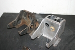 | January 24, 2010 - I love my bead blaster.
That's the pedal box for the boosted brakes on the right, with the unassisted setup on the right.
entry 259 - tags: brakes | | | 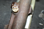 | January 24, 2010 - After a fair bit of calculation, I'm starting to figure out my brake options.
From my measurements, it looks like the MG brake pedal has a ratio of 4.48. That means that 100 lbs of pressure on the pedal is transformed into 448 lbs on the master cylinder. It also means that it takes 4.48" of pedal movement to move the master cylinder pushrod by 1". Basically, it's the same as a gear ratio. The Miata pedal has a ratio of 4.1 according to the manual.
I know the Miata setup pretty well, and the Targa Miata uses the hydraulics from a later Miata setup. The standard Miata master cylinder is a 7/8" unit, and the Sport master is 15/16".
As you can see from the picture, the stock MG master cylinder is 13/16".
So, based on pedal ratios and master cylinder sizes, I compared how much force on the pedal is needed to get 250 psi of line pressure. Why 500 psi? No reason, it's just a constant so I can get an idea of how the different setups would compare in feel for the same amount of braking. I also figured out how far the pedal would have to move in order to push 1 cubic inch of brake fluid, as the leverage ratios and hydraulic multiplication always trade off travel for effort. Here's what popped out of my spreadsheet:
- MG pedal, MG master: 57.87 lbs, 4.32"
- Miata standard setup: 73.3 lbs, 3.41"
- Miata Sport setup: 84.2 lbs, 2.97"
- MG pedal, 1" Wilwood master: 87.7 lbs, 2.85"
So no surprise here, the further you move the pedal the less you have to push on it. Simple leverage. And if you're doing these calculations at home, remember that it's a dual circuit system so you'll get half the pressure and twice the fluid flow as you would with a single circuit of the same size.
According to my calculations, a 15/16" master on the MG pedal (77 lbs, 3.25")would be pretty much right between the two Miata types. But the dual circuit remote reservoir master cylinder available from Wilwood is a pretty unusual piece, and only available in a 1" bore. I need the remote reservoirs to clear the hood, I believe. I do have a few other single circuit master cylinders I can use for test fitting for clearance.
Still, since Janel and I both prefer a nice firm pedal, I'll probably go with the Wilwood 1" setup.
But of course, there's a catch. The booster. All the calculations above give the numbers for an unassisted brake setup. The booster will multiply the force on the pedal to give more force at the master. If the booster has a 2:1 boost ratio, that means it would only take a bit less than 44 lbs of force on the pedal to generate my 500 psi of line pressure, instead of 87.7. And here's the problem. I don't know what the boost ratio of the MG booster is. The Miata one should be around 4.6 according to the manual.
So the end result is going to come down to trial and error, with a bias towards a too-firm pedal instead of a too-soft one.
This stuff is fun. I get to learn all sorts of things.
entry 260 - tags: brakes | | |
|

 THE DIARY