| THE MG |
|
|
 | |  | February 16, 2010 - With the harness simplified, I laid it out over the engine.
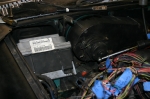
Next I had to find a place to stash the enormous ECU. It's huge! Newer ones are smaller - but I don't have a newer one. With the removal of the AC system inside the car, there's some room above the passenger's feet. It would be hard to disguise the big modern heatsinked box though.
The MGB, like many other Little British Cars, is ambidextrous and uses the same chassis for RHD and LHD applications. There are even plates covering over the holes where the pedals would pass through the firewall. This leaves a fairly large space where the RHD pedals aren't, and it's the perfect size for the ECU. As a bonus, the Camaro keeps its ECU in almost exactly the same place so the wiring lengths are almost perfect. I can even reuse the Camaro bracket.
It seems I get lucky with packaging once in a while on this project.
entry 288 - tags: wiring, packaging | | | 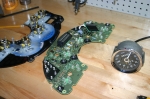 | February 16, 2010 - My plan has been to somehow stuff an electric speedometer inside the classic Smiths case.
The Camaro's T56 uses an electronic sender and the MG has a completely mechanical version.
Of course, I'm a long way from needing a speedo. But I'm not feeling completely healthy and poking around wires is more attractive right now than cutting and welding. Thus the electric emphasis of the last few days.
Well, it's not going to be easy. Looks like quite a challenge, actually. Enough of one that I started looking for alternatives. I already know of one, which is basically a small electronic motor in a box that takes an electronic signal in and spins a cable at the appropriate speed. It's a decent option, although a bit more of a kluge than I'd prefer. If you're converting a Miata with molded plastic gauges, you don't have a lot of other options. But the MG uses individual gauges, of course.
Poking around, I discovered that there actually exists an electronic Smiths speedo. It's not a perfect match to what I have, but it's awfully close. Close enough to work. And as a bonus, it's actually significantly less expensive than the little "gerbil box" motorized adapter. Excellent.
What about the tach? It's expecting a four-cylinder, so it'll read twice as fast with 4 pulses per crank revolution instead of 2. Some poking around pulled up an article on the British V8 site that explains how to add a potentiometer to easily make the tach adjustable. But wait, it gets better. 1972 was the only year to be fitted with a potentiometer from the factory. At the time the article was written, it wasn't known if this gave enough range to make it work with a V8, but I'm very willing to find out. If not, I'll just solder in a different one. Perfect.
entry 289 - tags: gauges, wiring | | | 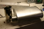 | February 20, 2010 - I've been trying to figure out what order to do things in right now, and I've decided to work on the exhaust.
I'm not really sure why that ended up at the top of the list, but there you go. It could be because the Super Turbo muffler I ordered showed up, and so now I know for sure there's enough room for it to fit.
The tip is one from a Flyin' Miata exhaust that I brought home to try for size and to see what Janel thought. She likes the style - they're really nice looking, with a double-walled tip with a constant outer diameter and a rolled inner shell - but thinks it's a bit big at 3.5". No worries, we have 3" ones as well which I think will be perfect. I like the slightly slanted tip.
Is it too early to pick out exhaust tips? Of course not!
entry 290 - tags: exhaust, tip | | | 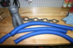 | February 20, 2010 - Of course, building the exhaust means building the headers.
I've been digging around trying to find recommendations on primary tube length, but to no avail. A diameter of around 1.625" or 1.75" seems to be the one to use, and since the last header I built used the latter I will probably do so again as I have some spare parts - including this collector.
The header flange is GM part 12480130, and it's 7/16" thick. Beefy! The blue pool hose? Well, that's how I do my initial layout testing. I'll figure out the general routing of the tubes first then fine-tune them with a very cool tool that will be making an appearance soon.
But there's no need for it. When I installed the steering column and started to figure out where the collector was going to go, it became obvious that there was no way to run a long-tube header in the car. I simply don't have the room - and that's with the collector in the wheel well! So it appears I'll have to settle for good flow instead of a nice extraction design. Oh well, it'll be an improvement over the stock units at least. And it should be easier to make this way.
entry 291 - tags: header, headers, exhaust | | | 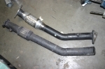 | February 20, 2010 - I saved these two Miata downpipes from the dumpster a few years back.
Flyin' Miata was moving and a lot of random, outdated parts were being sent to the scrapyard. Well, they're not much good as is. But they do have new stainless steel flex joints in them! So I'll cut those out and use them in the exhaust system. I don't expect the engine to move much, but it can't hurt.
Recycling at its finest.
entry 292 - tags: exhaust | | | 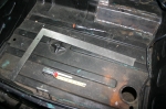 | February 20, 2010 - Before I can start fooling around with the exhaust, I need to confirm that the twin mufflers really will fit.
I'm almost positive they will, but it's time to move the gas tank. This is far less difficult than it sounds. The tank bolts to the bottom of the flat trunk floor. I simply had to drill a number of new holes 3" to the left of the existing ones. The large hole for the filler required a hole saw, but otherwise it was quick and easy work.
entry 293 - tags: fuel tank, packaging, exhaust | | | 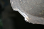 | February 20, 2010 - I did have to make one small alteration to the fuel tank.
This corner bumped up against my Panhard bar mount and kept me from getting the tank quite snuggled into position. A moment with the grinder solved that problem. You can see that the stock tank is actually crimped together. I was careful to stay clear of that section.
While I was goofing around underneath the car, I also removed the rear axle and relocated the lower shock mounting points an inch higher. This will give me a better bump/droop ratio for the suspension travel.
entry 294 - tags: axle, fuel tank | | | 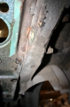 | February 21, 2010 - In order to fit the muffler under the car, I needed to take a chunk out of the wheel well.
You can see it at the lower right of the photo, it hasn't been cleaned up yet. Since the track is now wider than it used to be, this doesn't cause any sort of interference problem with the tires.
I also chopped a seam off the rear frame rail, visible at the top right of the photo. This rail was originally where the rear spring attached, so it saw some decent loads. But with the new coil spring setup, only the bumper is attached back here. By taking off the seam, I'll be able to move the muffler up by about 3/8". Hey, packaging is tight!
entry 295 - tags: exhaust, packaging | | | 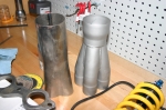 | February 21, 2010 - I've spent the weekend looking at exhaust options, figuring out how it will be routed and what components will make up the final design.
The two collectors in the picture are a couple from my collection. The grey merge collector on the right is an Edelbrock piece, one that I've used before in another build. I only have one of these.
The one on the left is of unknown parentage and will take more work to use as I'll have to cut and weld a star in between the tubes, while the Edelbrock is a slip-on. I have a pair of the basic ones.
The Edelbrock, being a merge collector, will theoretically flow better. But it has a 3" outlet (most collectors don't go much smaller) and I'll have to neck it down to 2.5" almost immediately - I'll use a Flowmaster ball joint connection to do that. So the benefit of the merge collector may be lost. The simpler one is also a 3" outlet, but it'll be shorter in length when assembled. The fact that I already have a pair of the simpler ones makes me think that's what I'll end up using.
I've been trying to figure out how to route the exhaust pipes over the axle. That leaves me short of space for an X-pipe, adds a bunch of bends and gets very tight just behind the axle. The idea is that running under the axle will be bad for ground clearance. But then I realized that the axle at full droop won't drop below the level of the floor pan. This means that if I run the exhaust pipes straight back, they'll clear the axle and ground clearance won't be affected at all! As an added bonus, it'll give me more room to run an X. Excellent. I just put in a big order for exhaust bits that will let me finish pretty much everything but the headers.
I thought I remembered the same thing being done on the Dan Masters build. I checked the photos and yup, it should work.
I have pretty good ground clearance on this car. The lowest point will have right around 4.5" clearance from the ground.
My decision to do exhaust now actually makes sense. It's not as flexible in packaging as some of the other components. Once the exhaust is sorted out, I'll be able to determine the location of the fuel pump and filter as well as the lines to the front of the car, keeping the fuel away from the hot pipes wherever possible. The same goes for wiring. I'm also looking at the cooling setup, but more details will come on that.
This is a really fun part of the build.
entry 296 - tags: exhaust, packaging | | | 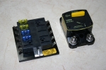 | February 26, 2010 - Parts are starting to arrive from all over!
Del City provided this 10-circuit fuse block. I figure I only need 6, but more can't hurt. The MG only has about 4 and they're all devoted to lighting from what I can tell. If I only need 6 of these 10, I'll integrate the two boxes.
I also picked up a big master circuit breaker. It'll give a bit of "uhoh" protection. It also lets me cut the power to the whole car, which is really handy when it comes time to work on things or to store a car for a while.
Most of the post-header exhaust parts are here as well, and the big box from AFCO will arrive Monday. I'll have no excuses for not working on the car shortly!
entry 297 - tags: wiring, exhaust | | | 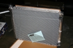 | March 1, 2010 - More parts have arrived!
This shipment is from AFCO. Along with some interesting suspension bits for the Targa Miata came this radiator. It's a dual-pass setup for maximum efficiency and it's huge! Seriously, it's the smallest rad I found that I thought would work and it's also the biggest radiator I thought I could fit: 26" wide and 20" tall. There's going to be some serious surgery ahead to make this work, and I think it's going to also entail hood pins. I just hope I can make it fit without hanging it down below the body.
There was one more option, a Scirocco style unit. Nice and small, also a dual pass. But the core size is 12.5 x 18", and my current rad is 18.5 x 22.5". That Scirocco one is just tiny. There are also some single-pass units that are a bit smaller, but the dual pass packages better in terms of outlet location.
Eek, this is going to be a challenge. At least I know that, once installed, this car will be immune to overheating. I hope.
entry 298 - tags: cooling, packagin | | | 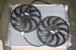 | March 1, 2010 - Despite the huge size of the radiator, it's a bit of a challenge to fit fans.
These are 12" units, and I guess this staggered setup will work. It's either that or one huge 18", and that would put the motor in the worst possible place. Given the fact that there are no heat exchangers (such as intercoolers or AC condensers) in front of the rad and pretty clear airflow, I think even two unshrouded fans like this will do the job. I'm very concerned about the depth of the assembly, as the more I push the rad forward the less hood height I have to play with - and I'm already tempting fate there.
entry 299 - tags: cooling, fans | | | 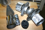 | March 1, 2010 - Exhaust bits!
Most of these have been around for a week or so while I continue to do nothing at all with them. The ball flanges on the right will join my headers to the main pipes, with some room for "oops". The shiny band clamp was also going to perform a similar task, but may be out of a job.
The rubber donut is an interesting bit - it's from a 1999-05 Miata and looks almost identical to a 1990-97 version. But it has a bit more rubber in the middle where the earlier unit has a void and is thus stiffer. Since I'm concerned about keeping my exhaust fairly constrained to avoid hammering on - well, everything - I decided to go with the stiffest one I could. Naturally, they're twice as expensive as the others. Hopefully I won't need TOO many of them!
The cone is intended to slip inside a collector to cut down on exhaust noise. Since the open area is actually greater than that of a 3" pipe, they claim little power loss and a 2-3 dB sound drop. I think I'll hold these in reserve, just in case. Janel wasn't excited about the new car parts, but she was almost hostile to the thought of making the car quieter!
entry 300 - tags: exhaust, noise | | | 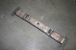 | March 4, 2010 - Driveshaft time.
I've managed to come up with a plan of attack to get me to the First Start of the engine. The exhaust is very high on the list as it's hot and big and determines where many other things go, but before I put the exhaust in I wanted to make sure the driveshaft wouldn't cause a clearance problem with the X pipe.
I'd forgotten to remove the driveshaft from the Camaro, so I jacked it up and pulled the shaft out. Easy, other than the remaining snowbanks and the joy of working on gravel. Don't worry Mom, I had some very large and thick boards under the jackstands to keep them stable!
After a lot of measuring and calculating and measuring again, I cut the driveshaft in half. This was a fairly painstaking cut, as I wanted to make sure it was completely square to the shaft itself. Once that was done, I spent some noisy quality time with the grinder removing the weld off the yoke for the pinion end so I could insert it back into the shortened shaft. More measuring with my new, shorter shaft and I cut off another 0.75". The yoke was an extremely tight fit into the tube, but I was able to coax it in eventually with the assistance of a precision 3lb sledgehammer and some careful placement.
Then I said "hang on a second", double-checked and removed the yoke again. I had it 90 degrees out of phase with the front one, they're supposed to be in phase. Out came the hammer again. When I test-fit the final result in the car, it was all sunshine and happiness in the shop. I'd been aiming for 0.75" to 1" of slip, and I ended up with 0.875". Right in the middle.
To avoid any nasty vibration problems down the road, I took the result to a local driveline shop for alignment, welding and balancing. He checked to see if the yokes were aligned, and was impressed to see that I'd managed to line them up perfectly. I think I was 0.5 degrees off, but apparently this is not a problem!
So what's in the picture? That's my transmission mount. As part of this exercise, I realized the transmission had to move over about 0.375". So I chopped it up and reassembled it to the correct dimensions. This makes it possible to install the driveshaft with the engine in the car! It'll also mean less modification to the transmission tunnel for the reverse lockout solenoid in the future. That's still coming up!
I forgot to take pictures of the driveshaft work, so it will make its public debut in a couple of days. Once I pick it up from the driveline shop, there's that step done!
entry 301 - tags: driveshaft, | | | 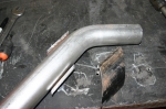 | March 4, 2010 - Now that the driveshaft is done - at least, my part of it is - it's time to take on the exhaust.
This has to pass through a frame crossmember in order to get from front to back, and I realized it would package better if it did so at a 45 degree angle. I picked up some pipe with an ID a bit bigger than the exhaust OD. It's some sort of massive gas pipe, and my poor chop saw had a heck of a time with it!
I sectioned my 45 degree piece to match it to the thickness of the crossmember. To make things interesting, the crossmember tapers in height as it heads towards the sill. So the pipe insert had to be different heights at each corner. Careful measuring, and voila. Ready to weld in once I've cut out the crossmember.
On further reflection, I'm thinking this might actually be best if I leave the pipe as a round pipe. That'll retain more strength (not sure if it's needed here, but still) and will make the lowest point of the car a piece of very burly pipe instead of a thin exhaust pipe. It'll still have approximately 4" of ground clearance, but it's at the breakover point. We'll see, I can always weld this bit back together. And yes, I have considered how I'll remove the exhaust without cutting it up!
entry 302 - tags: exhaust, packaging | | | March 7, 2010 - The plan for today was to complete most of the exhaust system.
To do this, I have to cut a half circle out of that crossmember to install my round insert. And this proved to be no fun at all. In fact, the only tool that was willing to do the job was the angle grinder, and due to the shape of the cutout the only way to do that would be to nibble it away piece by piece. My air-powered saw is nothing but an exercise in frustration. What I really need is a plasma cutter.
And there's a plasma cutter at work. Okay, sometimes I do have access to special tools! I'll see if I can bring it home on Monday. Then, instead of hours showering myself with sparks, I'll chop out that metal in about 5 minutes. Hopefully without setting myself on fire, but you can't have everything.
entry 303 - tags: exhaust | | | 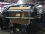 | March 7, 2010 - Since the exhaust was off the menu for the day, I turned my attention to the radiator.
It really is a monster. I chopped out more of the sheetmetal in the nose and tested to see how high I could put the rad with the hood closed. Had I specified the rad without a filler cap, it would have been a bit higher. Naturally the rad is just wide enough to cause interference with the structure of the hood.
Still, it's not quite as bad as this picture makes it look - which is pretty bad. At this height, the bottom of the radiator is approximately an inch below the front bodywork and about the same distance above the steering crossmember behind it - these are eyeball measurements, I haven't confirmed the exact dimensions. It has 6" of ground clearance. If I decide to install the MG Special Tuning airdam I picked up last spring, the radiator tucks in nicely behind. So we'll call that good then.
Due to the size of the engine and my decision to use (very slim) electric fans behind it, I have the radiator sitting quite far forward. If I were to put the fans in front of the radiator, I could move the whole thing back and gain myself some more clearance. This would make the fans less effective, but it's worth considering. After all, I think I have a slightly over-specified cooling system at the moment...
entry 304 - tags: radiator, cooling | | | 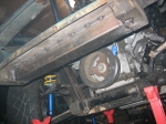 | March 7, 2010 - In order to fit the radiator, I had to remove some structure from the nose.
Of course.
I'd already cut the frame horns in half to fit the engine. There was a box that joined the remaining bits in half that was fairly nicely built with big lightening holes. However, these holes were too tempting for someone who had to tow this car at some point, so the box was rather torn up. Since I'd cut into it to fit the radiator, I decided to remove it completely. This had a fairly dramatic effect on the structural integrity of this part of the nose!
I still need these frame horns, however. That's where the bumper mounts. And I needed a way to mount the radiator as well. Now that I had all the parts in hand, I was able to figure out how to build a frame extension for the nose. First, a piece of 2x3 tube to replace that box. I'll extend that further to the sides and tie it into the suspension uprights then drop some steel down under the radiator to support it.
I'm pretty happy with this. It was one of the unanswered questions of the build, and it's good to have it figured out.
The two jackstands closest to the camera are the ones that were supporting the radiator, so you get an idea of how it sits relative to the frame.
entry 305 - tags: structure | | | 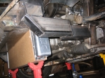 | March 7, 2010 - The structure at the front of the car is now finished.
Not fully welded - that'll happen when the engine is out - but complete. I'm really happy with this. The end result looks pretty obvious, but it took me a while to come up with it as I kept thinking "no, that's too complicated" and taking another look. This is simple, fairly light and should be decently strong. Might make a good sway bar mounting point in the future as well!
I was originally thinking of leaving the ends of the rail open (as can currently be seen on the cross bar) but realized that closing it off wouldn't just look better, it would also add some strength. So I closed 'em.
One detail you can't see on that cross bar is a couple of holes with nuts welded in the backside. Those will be alternate bumper mounting holes, since the originals are now trapped inside the cross bar.
It's quite easy to picture the location of the radiator in this shot, as it's actually in place.
entry 306 - tags: frame, radiator | | | 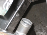 | March 7, 2010 - As usual, everything's tight.
A bit too tight, in fact. When I had the new frame horns and decided to install the rad to show off to Janel what I'd accomplished, I discovered that the radiator outlet was right into the kink in the horn. Argh. So I cut that one off again, chopped 5" off the back end and spliced it into the middle. You can see the ground-down welds in this shot. There still isn't a lot of room for the radiator outlet, but there's enough. That's all I ask.
On the other side of the engine, the alternator has a massive half inch of clearance. Ha, that's miles of room.
Speaking of clearance, I realized that my thought about using pusher fans and moving the rad back wouldn't work. The coolant outlet on the block would get in the way. So nix that idea then. I've decided I'm probably going to use 11" fans instead of the pair of 12" I was trying earlier, as then I can mount them side by side low on the rad. It'll mean most of the airflow will be concentrated on the bottom 2/3 of the core, but since it's a dual-pass setup it'll still hit all the coolant. This gives me more room.
entry 307 - tags: fans, packaging, frame | | |
|

 THE DIARY