| THE MG |
|
|
 | | 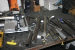 | May 18, 2010 - The debris of header building.
They were built out of mandrel U bends. If I have the count right, it took one with a 2.5" radius, one 2" radius, four 3" radius and a couple of other bits and pieces that were left over from previous projects. The primary tools were a chop saw and a belt sander.
entry 329 - tags: headers, exhaust | | | 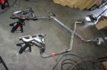 | May 22, 2010 - The exhaust is finished!
After making sure all the tack welds were strong enough and wouldn't shift, I dragged the whole thing out from under the car and finished the welding. It's built in five pieces - the main one with the X and the mufflers, two short hockey stick pieces with the ball joints for the headers, and the headers themselves. Right now, it's all hung with five hangers and I'll probably up that number somewhat.
But it's done! Woohoo!
entry 330 - tags: exhaust | | | 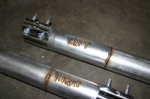 | May 22, 2010 - The two hockey stick pieces are pretty much clones of each other.
They should be identical. But just in case they're not, I labelled them!
entry 331 - tags: exhaust | | | 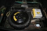 | May 22, 2010 - The batteries (yes, there were originally two) in the MG are supposed to live in some nicely hidden battery boxes just in front of the rear axle.
It's a pretty good use of space, they sit on each side of the differential nose which is easily a wasted area. But unfortunately, my exhaust system just touches the boxes on the bottom. I can raise the bottom of those boxes, but my Odyssey battery is just a bit too tall to allow me to do that.
In stark contrast to that particular packaging cleverness, there's a big empty space under the trunk floor. It originally held a full size spare and, well, not much else. Random tools, I suppose. If I install a space-saver spare in there, there's enough room for my Odyssey battery to lie down in the corner. I'll close in the battery boxes and use them for hidden storage, and this makes a bit of use of that weird basement to the normal trunk.
entry 332 - tags: battery, packaging, spare tire | | | May 23, 2010 - I spent part of the day running around looking for a way to connect a new line to the fitting on the MG gas tank.
Naturally, it's some oddball size that was probably created by the Romans and not used anywhere outside MG since 1982. But I think I've got that figured out. The fuel pump is mounted and I'm waiting for a couple of 45 degree fittings to arrive so I have everything I need. It actually won't take long to plumb things together once I have them, I think anchoring the main feed line will take longer than anything else.
I also started mounting the radiator - I'm trying to get most of the metalwork out of the way before I clean up and start running fuel lines and wires. There were a few false starts here as I tried to figure out a good, clean way to mount it. I've got some brackets welded in now that will do the job, but they're not as clever as I'd like and I'm probably going to add a cross bar under the rad to act as some impact protection. The hood closes and there's 6" of clearance under the rad - I consider that a victory!
entry 333 - tags: cooling, radiator, fuel | | | May 25, 2010 - I once wrote a short article for Grassroots Motorsports on "how to finish a project".
One of the tips - from the Locost community - is to spend 15 minutes a day in the garage. Even if it's just to pick up a few tools, it keeps the project active and who knows, you just might do something.
Well, I took my own advice last night. I was tired and didn't feel like working on the car, but I found myself in the garage looking at it. I spent some time looking at my radiator mount and came up with a better idea. Out came the steel and I fired up the chop saw and welder - and before I knew it I had a new crossmember/support for the radiator designed and built. It looks better, it's stronger, it'll protect the radiator, it gives me a place to mount some air ducting and it still has 5" of clearance under the bottom of the brace. More importantly, when I was done, I didn't feel as tired and I'd accomplished something!
Although I wasn't quite accomplished enough to take pictures. Those will follow.
entry 334 - tags: radiator, motivation | | | 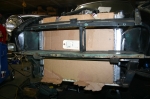 | May 27, 2010 - The radiator is mounted!
This is not a great picture of it, but you can see the new crossmember that runs underneath the rad. I spent a surprising amount of time on this, but the end result is solid, has 5" of ground clearance, supports and protects the radiator and allows for a simple drop-in installation.
It does drop down below the standard nose. Painted black, that might not show. The Special Tuning front air dam I picked up last year (!) is almost exactly the same depth, which will not only hide the rad but will also help me manage some good airflow. We'll see how it looks when painted.
entry 335 - tags: radiator, air dam, cooling | | | 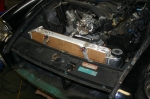 | May 27, 2010 - Here's the upper mounting for the radiator.
The bottom of the end tanks sit on rubber pads, providing most of the support. These rubber bushings keep everything in place up top. Simple and easy to install. The radiator is well secured as well. It's also sitting a bit lower than it has to, but a bit more hood clearance doesn't hurt.
entry 336 - tags: radiator | | | 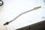 | May 27, 2010 - The first step in the fuel system - at least, from the point of the fuel.
The flare on the fuel tank is some weird British size, so I attached a new fitting to a short piece of the original fuel pipe. The fit on the compression fitting is so tight that I had to stick the pipe in the bead blaster and clean off the surface crust before it would slip over. The cleaner pipe will help it seal as well.
The two missing adapters I need showed up today in ludicrously large boxes, so I have everything I need to finish the fuel lines. I also started working on the wiring, and I've decided where the ECU will go. It'll be fairly straightforward from here.
entry 337 - tags: fuel, wiring | | | 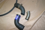 | June 1, 2010 - I decided to get the coolant lines finished so I could call the cooling system done.
Well, done except for an overflow tank and the heater, but I can cope without those for a bit. And I found a problem.
The radiator I have came with what I thought were the perfect inlet and outlet sizes. Big ones - 1.5" at the top and 1.75" at the bottom - but for some reason I thought that was exactly what I need. Oops. The Camaro radiator has 1.375" inlet and outlet. So I not only had to deal with a radiator sitting quite close to the engine, but also a size change in my hoses.
This is the resulting lower one. The Camaro part (top piece) was actually the perfect size but of course it wouldn't fit the radiator. I found a short 90 degree bit that did the job. The join is in a bit of an awkward place, but a curved piece of pipe took care of that. Voila. Sorted.
entry 338 - tags: radiator, hoses, cooling | | | 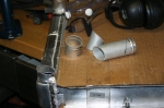 | June 1, 2010 - The upper hose was more of a challenge.
The lack of space between the radiator and the engine was a problem here, and I also had to find room to alter the size of the hose. So I decided to turn the fitting by 90 degrees and change the size at the same time. This will end up with a 1.375" fitting running parallel to the top of the radiator, allowing me to simply cut down the factory upper radiator hose. I'm hoping one of my coworkers - a TIG magician - can stick all these pieces together for me. I can do it, but it'll look pretty ugly.
entry 339 - tags: cooling, radiator | | | 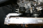 | June 6, 2010 - Tyler at Flyin' Miata stuck all the bits of my upper hose fitting together for me.
Nice work! I have welded aluminum in the past, but I prefer to save my stumbling around for less critical applications. Having the fitting (I think it's actually an outlet on an LS engine) turned 90 degrees like this makes things so much easier.
entry 340 - tags: cooling, radiator | | | 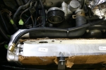 | June 6, 2010 - The final result.
The upper radiator hose from the Camaro was trimmed down and fits perfectly. A hole was drilled and tapped in the top of the radiator (through a boss Tyler welded in there for this purpose) and a fitting for the steam line was threaded in. And that's the radiator modifications done. I haven't done anything with the heater hookup yet, but that's a fairly quick job.
entry 341 - tags: radiator, cooling | | | 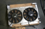 | June 6, 2010 - The fans will be mounted to the radiator something like this.
Obviously, I've just laid the fan shroud from a different car on to the radiator, but the theory is there. I'll make a similar shroud that covers the whole radiator, and the fans will be these two in approximately the same place. I think it should cool well.
entry 342 - tags: radiator, fans, cooling, shroud | | | 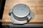 | June 8, 2010 - A mysterious device I found while connecting the return line.
I think it's a swirl pot of some sort - it was mounted vertically with one of the fittings (marked "IN" here) at the top. The return line from the regulator came into this upper fitting, then the lower one returned to the tank. The little doodad was sitting higher than the tank, so that would work.
Anyone know for sure?
entry 343 - tags: fuel, mystery | | | 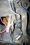 | June 8, 2010 - The fuel system is done!
It looks pretty nasty in this picture, partly due to the random wires of various sizes floating around and also due to some weird angles. The angles were chosen so I could use 45 degree fittings instead of 90 degree for less restriction. I also had to squeeze all the components into a fairly small space, of course.
The fuel comes from the tank through the 3/8" feed line, the leftmost one at the top of the picture. It's then adapted up to 1/2", because that's the size of the inlet on the pump. I didn't use 1/2" for that entire stretch because the actual line coming out of the tank is probably 5/16". The fuel then runs to the Corvette fuel filter, which doubles as a regulator. The braided stainless line at the bottom is a -6 AN line (3/8") that runs all the way up to the engine. The return line runs back to the tank through the factory swirl pot mystery cylinder at the moment. The stainless feed line runs through the transmission tunnel and is well anchored to keep it safe and to keep it from sawing through other things.
It took a remarkably long time to get all this done. Not only did I keep having to source adapters, but even securing the stainless line involved crawling under the car, measuring for a hole, drilling from above, crawling underneath to check the location, crawling back out to tack-weld the bolt into the hole, then going back under to bolt it up. Then move on to the next spot and do it again. Add to that the usual "whoops, I left my pen/ruler/wrench/fitting/drill on the table" up and down routine, and it seems as if I spent most of my day simply going under the car and back out again!
entry 344 - tags: fuel | | | 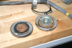 | June 9, 2010 - Mystery solved!
The "swirl tank" is actually a vapor separator as part of the emissions control system. What I thought was a return line was actually a vent for the fuel tank. The vapors collected in the separator traveled up to the engine bay into a charcoal canister and were eaten by the engine. Having the separator in place kept raw fuel from getting fed to the charcoal canister when a full fuel tank would expand from heat.
I can hijak the system to work as my return line - but then there's no venting capability for the tank. Older MGBs had a vented gas cap that let the pressure in the tank stay constant regardless of temperature fluctuations or fuel use. The downside is that they can drool fuel with a full tank on a hot day.
Luckily, the green MG parts car that lives outside is a 1969, and comes with the vented cap (on the right) and appropriate fuel filler tube. Since the charcoal canister from the 1972 car was damaged when I got it, that's my best solution. Looks like I might need to get a new cap though.
entry 345 - tags: fuel | | | 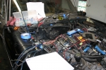 | June 16, 2010 - Wiring time!
This means I'm referencing a handy four-page schematic of the Camaro wiring, the one-page diagram for the MG and referring to the big 100-page book of Miata wiring once in a while. The Camaro wiring is actually going pretty well. The biggest problem is hunting down and fixing a couple of connectors that were damaged either when I pulled the engine or beforehand.
Integrating it into the MG wiring is a bit more challenging, although it did help when I figured out I was trying to reinstall the MG harness the wrong way in the car! I think I need to make a photocopy of the MG diagram and start identifying which sections to keep and which ones will be deleted.
Sharp eyes (and real obsessives) might notice that I've flipped the fuel rail over on the engine. This puts my fuel feed on the passenger's side instead of the driver's. It's just a bit easier to run it that way. Let's hear it for symmetrical intake manifolds!
entry 346 - tags: wiring, fuel | | | 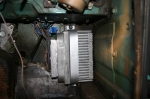 | June 16, 2010 - One of the big roadblocks to the wiring was figuring out how to mount the massive ECU.
As you may remember, I was originally going to put it in the engine bay, but that was a pretty tight fit. I was also trying to reuse the stock bracket, and that was proving to be difficult. There's a bracket from the S10 or some sort of van that is a bit easier to mount in a non-standard location and arrangement, but I finally realized I could simply mount it with a solid strap, as seen here. It's solid and secure, but easy to remove when needed.
The ECU is located at the end of the passenger's footwell, which means the wiring harness can easily drop down through the hole that would have been used for the pedals in a RHD car. Cool. I'll probably put a plate over top of it to hide the ECU and give the passenger a good solid foot rest - but not yet.
entry 347 - tags: ECU, wiring, packaging | | | 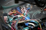 | June 16, 2010 - The GM computer needed a few new circuits.
The MG only has five fuses (that I know of) in the entire car, but I wanted more than that! To be fair, one of the fuses in the new box is a duplicate of the fuel pump fuse in the old one - I'm not sure if I'm going to retain that particular one.
The wire colors here are the GM ones, they're quite fond of pink wires. Thus the labels. The wires will be corraled further when I'm done as well, right now they're just being roughly loomed together.
The new fuse box sits in the engine bar, where the pedal box would be on a RHD car. The square hole at the bottom of the picture is the one that lets the wires run down to the ECU, which is just barely visible in there. I'll adapt the factory cover to make this look good.
entry 348 - tags: wiring | | |
|

 THE DIARY