| THE MG |
|
|
 | |  | March 1, 2010 - Exhaust bits!
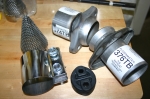
Most of these have been around for a week or so while I continue to do nothing at all with them. The ball flanges on the right will join my headers to the main pipes, with some room for "oops". The shiny band clamp was also going to perform a similar task, but may be out of a job.
The rubber donut is an interesting bit - it's from a 1999-05 Miata and looks almost identical to a 1990-97 version. But it has a bit more rubber in the middle where the earlier unit has a void and is thus stiffer. Since I'm concerned about keeping my exhaust fairly constrained to avoid hammering on - well, everything - I decided to go with the stiffest one I could. Naturally, they're twice as expensive as the others. Hopefully I won't need TOO many of them!
The cone is intended to slip inside a collector to cut down on exhaust noise. Since the open area is actually greater than that of a 3" pipe, they claim little power loss and a 2-3 dB sound drop. I think I'll hold these in reserve, just in case. Janel wasn't excited about the new car parts, but she was almost hostile to the thought of making the car quieter!
entry 300 - tags: exhaust, noise | | | 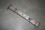 | March 4, 2010 - Driveshaft time.
I've managed to come up with a plan of attack to get me to the First Start of the engine. The exhaust is very high on the list as it's hot and big and determines where many other things go, but before I put the exhaust in I wanted to make sure the driveshaft wouldn't cause a clearance problem with the X pipe.
I'd forgotten to remove the driveshaft from the Camaro, so I jacked it up and pulled the shaft out. Easy, other than the remaining snowbanks and the joy of working on gravel. Don't worry Mom, I had some very large and thick boards under the jackstands to keep them stable!
After a lot of measuring and calculating and measuring again, I cut the driveshaft in half. This was a fairly painstaking cut, as I wanted to make sure it was completely square to the shaft itself. Once that was done, I spent some noisy quality time with the grinder removing the weld off the yoke for the pinion end so I could insert it back into the shortened shaft. More measuring with my new, shorter shaft and I cut off another 0.75". The yoke was an extremely tight fit into the tube, but I was able to coax it in eventually with the assistance of a precision 3lb sledgehammer and some careful placement.
Then I said "hang on a second", double-checked and removed the yoke again. I had it 90 degrees out of phase with the front one, they're supposed to be in phase. Out came the hammer again. When I test-fit the final result in the car, it was all sunshine and happiness in the shop. I'd been aiming for 0.75" to 1" of slip, and I ended up with 0.875". Right in the middle.
To avoid any nasty vibration problems down the road, I took the result to a local driveline shop for alignment, welding and balancing. He checked to see if the yokes were aligned, and was impressed to see that I'd managed to line them up perfectly. I think I was 0.5 degrees off, but apparently this is not a problem!
So what's in the picture? That's my transmission mount. As part of this exercise, I realized the transmission had to move over about 0.375". So I chopped it up and reassembled it to the correct dimensions. This makes it possible to install the driveshaft with the engine in the car! It'll also mean less modification to the transmission tunnel for the reverse lockout solenoid in the future. That's still coming up!
I forgot to take pictures of the driveshaft work, so it will make its public debut in a couple of days. Once I pick it up from the driveline shop, there's that step done!
entry 301 - tags: driveshaft, | | | 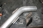 | March 4, 2010 - Now that the driveshaft is done - at least, my part of it is - it's time to take on the exhaust.
This has to pass through a frame crossmember in order to get from front to back, and I realized it would package better if it did so at a 45 degree angle. I picked up some pipe with an ID a bit bigger than the exhaust OD. It's some sort of massive gas pipe, and my poor chop saw had a heck of a time with it!
I sectioned my 45 degree piece to match it to the thickness of the crossmember. To make things interesting, the crossmember tapers in height as it heads towards the sill. So the pipe insert had to be different heights at each corner. Careful measuring, and voila. Ready to weld in once I've cut out the crossmember.
On further reflection, I'm thinking this might actually be best if I leave the pipe as a round pipe. That'll retain more strength (not sure if it's needed here, but still) and will make the lowest point of the car a piece of very burly pipe instead of a thin exhaust pipe. It'll still have approximately 4" of ground clearance, but it's at the breakover point. We'll see, I can always weld this bit back together. And yes, I have considered how I'll remove the exhaust without cutting it up!
entry 302 - tags: exhaust, packaging | | | March 7, 2010 - The plan for today was to complete most of the exhaust system.
To do this, I have to cut a half circle out of that crossmember to install my round insert. And this proved to be no fun at all. In fact, the only tool that was willing to do the job was the angle grinder, and due to the shape of the cutout the only way to do that would be to nibble it away piece by piece. My air-powered saw is nothing but an exercise in frustration. What I really need is a plasma cutter.
And there's a plasma cutter at work. Okay, sometimes I do have access to special tools! I'll see if I can bring it home on Monday. Then, instead of hours showering myself with sparks, I'll chop out that metal in about 5 minutes. Hopefully without setting myself on fire, but you can't have everything.
entry 303 - tags: exhaust | | | 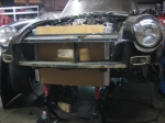 | March 7, 2010 - Since the exhaust was off the menu for the day, I turned my attention to the radiator.
It really is a monster. I chopped out more of the sheetmetal in the nose and tested to see how high I could put the rad with the hood closed. Had I specified the rad without a filler cap, it would have been a bit higher. Naturally the rad is just wide enough to cause interference with the structure of the hood.
Still, it's not quite as bad as this picture makes it look - which is pretty bad. At this height, the bottom of the radiator is approximately an inch below the front bodywork and about the same distance above the steering crossmember behind it - these are eyeball measurements, I haven't confirmed the exact dimensions. It has 6" of ground clearance. If I decide to install the MG Special Tuning airdam I picked up last spring, the radiator tucks in nicely behind. So we'll call that good then.
Due to the size of the engine and my decision to use (very slim) electric fans behind it, I have the radiator sitting quite far forward. If I were to put the fans in front of the radiator, I could move the whole thing back and gain myself some more clearance. This would make the fans less effective, but it's worth considering. After all, I think I have a slightly over-specified cooling system at the moment...
entry 304 - tags: radiator, cooling | | | 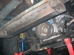 | March 7, 2010 - In order to fit the radiator, I had to remove some structure from the nose.
Of course.
I'd already cut the frame horns in half to fit the engine. There was a box that joined the remaining bits in half that was fairly nicely built with big lightening holes. However, these holes were too tempting for someone who had to tow this car at some point, so the box was rather torn up. Since I'd cut into it to fit the radiator, I decided to remove it completely. This had a fairly dramatic effect on the structural integrity of this part of the nose!
I still need these frame horns, however. That's where the bumper mounts. And I needed a way to mount the radiator as well. Now that I had all the parts in hand, I was able to figure out how to build a frame extension for the nose. First, a piece of 2x3 tube to replace that box. I'll extend that further to the sides and tie it into the suspension uprights then drop some steel down under the radiator to support it.
I'm pretty happy with this. It was one of the unanswered questions of the build, and it's good to have it figured out.
The two jackstands closest to the camera are the ones that were supporting the radiator, so you get an idea of how it sits relative to the frame.
entry 305 - tags: structure | | | 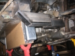 | March 7, 2010 - The structure at the front of the car is now finished.
Not fully welded - that'll happen when the engine is out - but complete. I'm really happy with this. The end result looks pretty obvious, but it took me a while to come up with it as I kept thinking "no, that's too complicated" and taking another look. This is simple, fairly light and should be decently strong. Might make a good sway bar mounting point in the future as well!
I was originally thinking of leaving the ends of the rail open (as can currently be seen on the cross bar) but realized that closing it off wouldn't just look better, it would also add some strength. So I closed 'em.
One detail you can't see on that cross bar is a couple of holes with nuts welded in the backside. Those will be alternate bumper mounting holes, since the originals are now trapped inside the cross bar.
It's quite easy to picture the location of the radiator in this shot, as it's actually in place.
entry 306 - tags: frame, radiator | | | 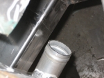 | March 7, 2010 - As usual, everything's tight.
A bit too tight, in fact. When I had the new frame horns and decided to install the rad to show off to Janel what I'd accomplished, I discovered that the radiator outlet was right into the kink in the horn. Argh. So I cut that one off again, chopped 5" off the back end and spliced it into the middle. You can see the ground-down welds in this shot. There still isn't a lot of room for the radiator outlet, but there's enough. That's all I ask.
On the other side of the engine, the alternator has a massive half inch of clearance. Ha, that's miles of room.
Speaking of clearance, I realized that my thought about using pusher fans and moving the rad back wouldn't work. The coolant outlet on the block would get in the way. So nix that idea then. I've decided I'm probably going to use 11" fans instead of the pair of 12" I was trying earlier, as then I can mount them side by side low on the rad. It'll mean most of the airflow will be concentrated on the bottom 2/3 of the core, but since it's a dual-pass setup it'll still hit all the coolant. This gives me more room.
entry 307 - tags: fans, packaging, frame | | | 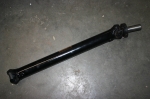 | March 15, 2010 - The finished driveshaft.
Okay, not a terribly exciting picture. But I'm pretty happy with how easy and inexpensive this was.
entry 308 - tags: driveshaft | | | 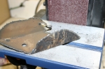 | March 15, 2010 - I dragged the plasma cutter home to chop out the stock frame rails.
It was a very quick and easy job as I'd hoped. I had my welding helmet set too dark so I couldn't see where I was cutting, but it only took a little bit of cleanup afterwards to make everything work well.
Plasma cutters rock.
entry 309 - tags: frame | | | 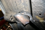 | March 15, 2010 - The frame rail pass-through tacked into place!
Compare the wall thickness of my new pipe to the picture of the removed part. I suspect the car is now stronger. And more importantly, the exhaust construction may now commence.
entry 310 - tags: frame | | | 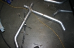 | March 15, 2010 - First step on the exhaust.
This is the section that goes through the new pass-through. Clearances are tight (no, really) but it works. The wide section at the bottom is the front half. I'll build the back section first, then start working on the header design. I'm thinking there will be rapid visible progress with this part, which is always satisfying.
entry 311 - tags: exhaust | | | 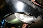 | March 16, 2010 - With the X located, I figured I needed to identify the other end.
So I hung the first muffler under the car. It took a bit of fiddling around to get the location sorted, but a couple of hangers and some careful placement and it was in place.
entry 312 - tags: exhaust, muffler | | | 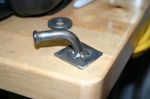 | March 16, 2010 - I needed a way to attach hangers to the bottom of the car.
The flat floor is a bit tough to weld to, so I welded the hanger to a small plate. The hanger itself is a piece of 1/2" bar bent to shape. I tried both a small kink and a bead around the end to keep the rubber from sliding off. Both seem to work pretty well.
entry 313 - tags: exhaust | | | 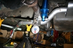 | March 16, 2010 - Once the muffler was in place, I was able to figure out the routing of the rest of the piping.
It's fairly straightforward. The only problem is the trailing arm bracket on the rear axle housing. It's nicely in line with the outlet on the muffler. The muffler is also higher than the axle at full droop.
A 45 degree piece out of the muffler, rotated about 45 degrees from vertical and mated to another 45 degree piece wiggled the pipe nicely around the obstacles. Nice and simple. I used jack stands to support the exhaust under the car - lots of jack stands. Once I figured out how, it went pretty quickly.
entry 314 - tags: exhaust | | | 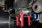 | March 16, 2010 - With one side of the exhaust done, now I have to do it all again - and make it symmetrical.
Uhoh. The first step is to position the muffler in exactly the same place. It's the most visible part of the system so I have to get this right. I won't weld hangers on this one until it's hooked up to everything else, to make sure I don't accidentally put a bit of variation in the system.
entry 315 - tags: exhaust, muffler | | | 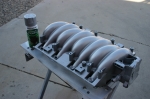 | March 24, 2010 - I can't do any work on the car for the next little while that involves flying metal, which is surprisingly limiting at this point of the build.
So instead, I took advantage of a nice sunny day to cast a spare intake manifold in aluminum. At least, that's what I'm hoping the result looks like. I figured the engine looks a little too plastic for the old car, so I shot my spare intake manifold with paint.
After some test sprays I decided a light hammered finish looked the most like metal. I think it'll be pretty good. I have to find some way to hide the coils that look appropriate. The proximity of the brake booster makes this a challenge. Maybe if I mount them remotely...
entry 316 - tags: intake | | | May 3, 2010 - Work has finally resumed.
I took some time off for lasik eye surgery (highly recommended), some engine work on the Targa Miata, a trip to Laguna Seca with three days at the track, etc, etc. But it's time to dig back into things.
I didn't get a lot of work done tonight - I repositioned the muffler in the perfect location again, then figured out how to snake the exhaust pipes past the Panhard bar mount on the axle at full droop and cut a couple of pipes - but it was a start. Expect more progress! Will the car run by the end of the month? It's possible...
entry 317 - tags: exhaust | | | 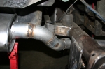 | May 10, 2010 - This was a fun little section to do on the exhaust.
The pipe has to twist around the Panhard bar mount on the axle and wiggle up to the muffler. And I had to do this while putting the muffler in the perfect place. The end result did have me welding up a bit of a gap - you can see the ugly resulting weld - but it'll do the job! It's just tacked together now, I'll clean everything up later.
Next step: hangers for this muffler. Then for the X-pipe. Then I do the headers.
Janel has a new job that keeps her traveling quite a bit during the week. This has shifted the timeframes I have available to work on the car - evenings are much easier to do, but weekends are pretty much out. I'm figuring it out now, so work should continue apace.
entry 318 - tags: muffler, exhaust | | | 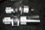 | May 12, 2010 - Exhaust work continues.
I now have the system complete up to the entrance to the x-pipe. Now I have to figure out the headers. My collectors have a 3" outlet and the rest of my exhaust system is 2.5", so I plan to use these ball flanges to neck things down while also providing a good spot to disassemble the exhaust. The problem is that the whole assembly is pretty long as you can see. I've cut down most of the parts and taken a significant amount of length out since this photo was taken. You can see the conical insert from Dynatech that should drop the sound level by around 2-3 dB.
I'd prefer to be using a slip-on collector as they're a lot easier to deal with than this minimalist one - but unfortunately, I don't have any. So I'll have to cope with it.
entry 319 - tags: exhaust, collector | | |
|

 THE DIARY