| THE MG |
|
|
 | | 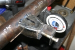 | December 2, 2009 - With the body mount in place, it's time to build the one on the axle.
I welded one of the threaded bungs into a length of 1" pipe and attached it to the body. Then the axle got put into place and I measured the distance from the bar to the axle. That gave me what I needed to figure out what the mount on the axle should look like.
I went through a number of possible designs for this. The final one - shown - has a bracket made of a section of 2x2 bar with a nice thick wall. It's welded to a support made of 2x3 bar, reshaped to meet up. There's a nut welded on the back side of the bracket. A lot of designs I see in circle track catalogs put the bolt in single shear instead of double like this, but I prefer this design.
entry 222 - tags: rear axle, panhard, suspension | | | 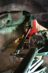 | December 2, 2009 - And voila!
The rear suspension linkages are all in place. The axle is sitting quite a bit lower than usual to show off the bar. In case you're wondering what a Panhard bar does, it provides the lateral support for the axle.
The two outer (lower) trailing arms keep the axle straight in the frame and transfer the brunt of the power to the chassis. The center link at the top of the diff keeps the whole thing from rotating under power and lets me set the pinion angle. And the Panhard bar transfers the side loads into the frame. With this whole lot in place, the axle can twist up and down to let the wheels follow the road, but it will always stay properly aligned to the chassis. Cool.
It's not completely finished, of course. I tucked that Panhard bar into a pretty tight spot, and it only clears the back of the axle by a millimeter or so. More importantly, the bracket on the axle hits the body of the car. A bit of reshaping will solve that problem, of course, but I think I'll have to pull the fuel tank to do it properly. No worries, that looks like a pretty straightforward job.
entry 223 - tags: panhard, suspension, rear axle | | | 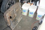 | December 2, 2009 - The tank came out without much fuss at all.
No recalcitrant fasteners, no further dismantling required for access. Thank you MG.
Of course, I had filled the tank with fresh fuel a year and a half ago when I was trying to run it on the original engine. So I had to drain out an amazing amount. Note the approved containers of fuel in the background.
entry 224 | | | 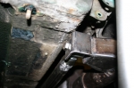 | December 2, 2009 - Here's the interference between the body and the Panhard bar mount.
It's not dramatic, there's only about an inch of up travel left anyhow. It'll be simple to add the space I need without any real consequences anywhere else.
At the top of the picture is the bracket that originally held the straps for travel limitation. I'm thinking it'll be a good place to put a sway bar end link.
entry 225 - tags: rear axle, suspension, panhard | | | 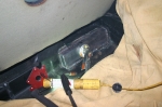 | December 10, 2009 - After filling the garage with smoke and setting the car on fire a couple of times, the body is reshaped to clear the Panhard bar mount.
The welding's a bit ugly as I had a bit of trouble getting a wire wheel in to clear up the floor properly, but it's not terribly structural so that's not important. I'll clean it all up with seam sealer before it gets repainted anyhow.
I'm not sure what to repaint with. There's some sort of goo or tar in there that isn't factory and likes to make a mess of my clothes - you can see some overspray on the bottom of the panel just above my new patch as well as the variation in color. This part of the trunk is hidden beneath the trunk floor and is just used for spare tire storage. It's big, though, and I'd love to put it to work for me somehow.
entry 226 - tags: trunk, rear axle | | | 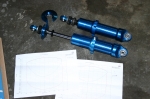 | December 16, 2009 - The shocks are here.
They're a set of custom single-adjustable T2s from AFCO. I worked with AFCO on the suspension for the Targa Miata and I was really happy with the process. Not just the final result, but the experience of working with the company. They're very responsive and willing to do all sorts of oddball things.
The custom shocks weren't that expensive, either. In fact, I probably would have spent more by going with a non-adjustable off-the-shelf coilover setup from someone else like QA1. I have a good collection of springs from previous projects, so I should be able to use those to get into the right ballpark. Most shocks in this price range have a fixed valving, which won't let me experiment with the suspension to get the ride and handling sorted out. Since I really don't have a clue what sort of rates I'll be running - particularly in the rear - I need the ability to swap springs around. The T2 has a huge adjustment range, so I won't have to get them revalved if I swap springs. I went with a single adjustment (rebound) as that's the more important one. If I want to upgrade them to a double-adjustable setup, that's a fairly easy change to make.
The shocks in the picture are for the rear. They've got a 5" stroke for some decent suspension travel back there. The upper perch comes off in seconds without tools, making it very easy to swap springs. The rubber bumper on the shock shaft isn't intended as a bumpstop, as I'll be using the factory MG one attached to the frame. The rubber's just there to protect the shaft seal in case of problems. The shocks are rebuildable if necessary. Oh, and the aluminum body is light, not that this is a big factor with a big heavy live axle.
Overkill? I don't think so. I like my cars to handle. The MG isn't just going to be a straight-line car. I picture it as a great touring car that just happens to have the ability to rip up a series of corners without breaking a sweat.
entry 227 - tags: suspension, shocks | | | 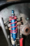 | December 16, 2009 - After a bit of cogitating, I built this lower shock mount for the rear axle.
I'm not completely happy with it, it's not as elegant as I'd like. But it should be strong enough. It's 1/4" plate, welded to the lower trailing arm bracket as well as to the axle tube. There's a triangular reinforcement taking care of some fore-aft strength. I'm still redesigning it in my head, we'll see. That lower shock mounting point carries the entire load of the car (well, 1/4 of it). Assuming the car is around 2600 lbs and evenly balanced (possibly both fairly big assumptions), that means there's 650 lbs on that perch. If it's designed for a 3g load, that means it has to support approximately 2000 lbs. I'll definitely be monitoring this!
The upper mounts will be attached to a plate that will spread the load somewhat. At least, that's my plan. We'll see how that works out.
Underneath the bumpstop, you'll see part of the original MG axle sitting on top of my axle tube. This means I'll have the same bump travel as the original suspension. I'm estimating a bit here, trying to set the shock up so it doesn't quite bottom out at full compression. I expect to have to do some fine-tuning in this area.
entry 228 - tags: rear axle, suspension | | | 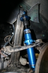 | December 16, 2009 - The front shock mounting is much easier to figure out.
The shock is basically the same design we worked out for the Miata application, but fitted with a different upper mount. The bottom bolts right in to the Miata control arm, and a simple bracket will take care of the top. Lots of clearance. I left that upright on the frame for this purpose, looks like I got the dimensions just about perfect. It'll be tied into the unibody and hopefully cross-braced across the engine bay once I know how much room is available to me.
entry 229 - tags: suspension, front suspension | | | 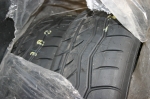 | December 16, 2009 - The new tires arrived as well.
Falken Azenis RT615s, nice and sticky. Not the latest and greatest ultra high performance street tire and cursed with a pretty stiff sidewall that wreaks havoc with ride, they're about the hottest thing you can get in the small 14" size I'm using. I could also go with Toyo RA1s, but I'd rather not have yet another car that runs R compound tires on the street!
entry 230 - tags: tires | | | December 17, 2009 - Every shock from AFCO comes with a dyno chart.
And not just a representative dyno chart, but one for that actual shock with the serial number on it. I had some questions about the dyno curves on my rear shocks so I sent an email off to my contact at AFCO. He printed out the charts for my particular shocks, checked them with a technician and replied back with details on what I was seeing.
Now that is why I like to work with them!
entry 231 - tags: suspension | | | 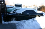 | December 26, 2009 - It's time.
My goals for my holiday are to get the MG on its wheels and to extract the drivetrain from the Camaro. Janel is a sick little kitten today and I needed something relatively quiet to do - so the Camaro it is.
First, I had to dig it out of the snowbank. It also needed a fair bit of coaxing to fire up, due to a battery that was about as dead as a battery can get. Finally, after about 45 minutes of shoveling, battery swapping and trying to convince the Camaro to move on ice - never a favorite hobby for the car - I got it into the garage.
Janel watched through the window from her sick bed.
entry 232 - tags: Camaro | | | 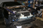 | December 26, 2009 - The first thing I did - which took about an hour - was to pull off the front bumper and other bits in the nose.
This made it a lot more comfortable to work on the engine as I could get close to it instead of having to deal with that stupendous schnozz. Seriously, it's like someone dared the designers to make the least space-efficient car possible.
entry 233 - tags: Camaro | | | 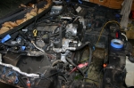 | December 26, 2009 - With the AC and radiator out, you can really see how far back the engine sits.
Remember, I've already removed at least a foot of proboscis from the car. Nice work Chevy on getting the engine so far back, but serviceability is definitely a problem.
entry 234 - tags: Camaro | | | 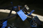 | December 26, 2009 - Naturally, all the wire connections (that I was able to identify) got labeled for future reference.
This will hopefully make life a lot easier in the future. Of course, as I went to actually remove the engine I discovered there were a number of connections right on the back of the engine. The sort that you only find out about as you're pulling an engine and it just doesn't want to move - and as far as I can tell, that's also the only way to access them!
entry 235 - tags: Camaro | | | 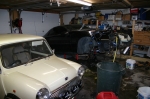 | December 26, 2009 - Due to the tight constraints of the engine bay, you have to pull the intake manifold off as well as remove the engine from the transmission to pull it out the traditional way.
The drivetrain was really intended to come out through the bottom. So I took a page from the Book of Working On Classic Minis and basically lifted the nose of the car off the engine, transmission and drivetrain as a unit. I dropped the engine on to some furniture dollies so I could simply roll it out from underneath.
I'm not sure the two cars have a whole lot more in common than than.
entry 236 - tags: Camaro | | | 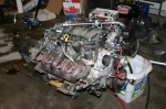 | December 26, 2009 - A fairly non-compelling but obligatory picture of the liberated engine and transmission.
The whole process took about 9 hours from starting with the shovel to saying "okay, that's enough for now".
I learned quite a bit about working on Camaros, slowly and methodically. One thing is that they have a clutch hydraulic setup that's basically sealed. I had to pull the master cylinder and a remote reservoir out along with the engine - and let me tell you, you can stretch that factory braided clutch line pretty far without it breaking! Also, the car has a "torque tube" that's very similar to that of a Miata, but it only locates the differential and not the transmission. I guess the fact that the differential has to move up and down in the live axle would make the more solid Miata solution unworkable.
I made an unholy mess as part of the process. Transmission fluid (whoops, didn't cap the output shaft), power steering fluid (whoops, broke a line when I tried to separate the engine from the subframe) and of course, my usual mess of coolant. It's all soaking up with kitty litter right now and I'll put the subframe back in the car tomorrow so I can push it back outside and reclaim an enormous amount of garage real estate.
I've mentioned before how this is a garage build, not one done with exotic tools or expensive facilities. This engine pull would have been a lot easier with a lift. As it was, I had ice water puddled all around underneath the car as it thawed out despite my best attempts to clean off the car. As I worked on the rusty exhaust on a creeper, the sleeves of my sweatshirt would dip into the water to give me a nice surprise the next time I'd move. Sometimes, for variety, I'd dip my pantleg in it instead.
The next person who claims I have access to special tools is going to get a poke in the nose.
entry 237 - tags: Camaro | | | 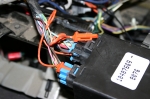 | December 31, 2009 - After the big dramatic day of pulling out the engine, I continued to work.
That great engine is worthless without the wiring to run it, so I spent several days pulling out what I needed. Yanking out a wiring harness without chopping it up requires fairly substantial disassembly of the car, including pulling the dash.
GM made some weird choices when it comes to connectors. Some are the excellent GM "Weatherpak" ones. But some of the parts that appear to be sourced from the outside use a wide variety of completely different connector designs. It's a bit ridiculous, making the wiring harness appear to have been designed by a half dozen teams that never actually talked to each other.
A number of connectors are locked in to place with a secondary pin. In the picture, the orange insert needs to be pulled out (which, in this case, involved a dental pick to depress the small and difficult to access tangs) before the blue section can be removed. Why? It certainly makes the car harder to assemble and to work on. Most of the other connectors have a more common clip that can be released easily. But for some reason, there's a guy at Chevy who's paranoid about how secure a connector has to be.
entry 238 - tags: wiring | | | 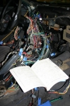 | December 31, 2009 - I'm trying to isolate the wires I need so I don't need to pull the entire harness from the car.
There are probably easier ways to go about this - more on that later - but I figure I'd rather put in the extra effort just in case.
Remember those disparate wire harness engineering teams that wouldn't talk to each other about connector design? They also didn't communicate on wire colors either. There simply aren't enough colors to go around, and the common trick of adding a stripe to distinguish between say, a white wire and a white wire with a green stripe. Adding the stripe increases the number of distinct wires dramatically. Instead, the instrument cluster has two white wires coming out of it. One is for the skip shift system, the other is the speedometer signal. Both go to the Powertrain Control Module or PCM. Thanks Chevy!
Now, the easier method. I just remembered that Painless makes an LS wiring harness. In fact, it turns out they make one for the unique 1998 Camaro PCM. It includes everything you need to run the engine and nothing else - even a fusebox - and is designed for jobs like mine. As a bonus, they'll also reflash your PCM for free, disabling the need to use a key with a particular resistor stuck inside or turning off the need for rear O2 sensors. The total is right around $500. When you consider I've probably taken $500 of potential resale out of the Camaro (should it remain a viable car, anyhow), I'll have to pay for the software to reflash the PCM and I may end up spending some money on a fusebox, it may have actually been a money-saving choice to make. Oh well, I'm committed to this plan now.
entry 239 - tags: wiring | | | 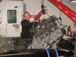 | December 31, 2009 - Because I was tired of wiring, and the engine was sitting right beside the car, I decided it was time to stick it in!
Janel came to help, as there's no way I could have done this myself. The MG is sitting sideways across the end of the garage, so first we had to carefully sneak the suspended engine and transmission around the front of the car, then push the crane sideways to feed the engine into the chassis.
It was a bit of a tight fit. Pulling the complete shifter out would have helped, but with some careful tilt/move/tilt/move we were able to wiggle the engine in to place. Well, almost.
Janel likes to be around for the big dramatic moments. Almost exactly a year ago, she was helping me hollow out the engine bay and pull the dash.
entry 240 - tags: Janel, engine, installation | | | 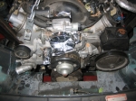 | December 31, 2009 - Here's why I knew I needed to fit the real engine instead of just my plastic one.
The pulleys and water lines and accessories make things more complex. And it became apparent pretty quickly that I needed to open up the front of the engine bay a bit more. Time to chop a bit more off the car!
entry 241 - tags: engine, destruction, first fitment | | |
|

 THE DIARY