| THE MG |
|
|
 | | 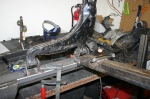 | January 28, 2009 - I picked up some more steel for the frame rails.
This new stuff has a thicker, 11ga wall and is hopefully straight. Step 1 was to weld on the front control arm mounting point, then I bolted up a control arm and used that to fixture the rear. Quick and easy. The relationship between the lower and upper control arms is handled by the fact that the front mounting point remained fixed to the upper one.
entry 154 - tags: suspension, frame | | | 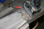 | January 28, 2009 - To minimize the chances of warping, I moved around the pieces to weld them.
The idea was to never let one area get too hot. The thicker wall also helps here.
entry 155 - tags: suspension, frame | | | 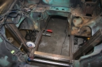 | January 28, 2009 - With the frame rails assembled, I cut them to shape to fit the floorpan, then tacked them into place.
They went in quite satisfactorily and with the angles all looking good. Then, to make sure, I stuck the steering rack crossmember in place after cutting it from a calculated (not measured) length. And it fit perfectly. Everything looks to be centered and the dial level is happy. So we're good! That didn't happen right away, I had to play around with it all for a bit until it all just clicked into place. Sharp eyes will notice that I did have to cut a slot in the frame rails and weld it up, using that to take out a small bit of warp from the welding. It's minor, but spread over a 4' length even half a degree could be problematic. But it's all good now!
I just need to fully weld the frame rails on, then I'll come up with some steering rack mounts. Then, once I know where the steering shaft will run, I can start reinforcing and integrating the new frame into the unibody. I'll also start massaging the transmission tunnel to fit the (huge) T56 transmission.
I feel as if I just unlocked the potential for a large percentage of the project to move ahead.
entry 156 - tags: suspension, frame | | | 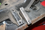 | January 28, 2009 - The next step is the steering rack mounts.
To behind, a fair bit of careful measurement. I want to try to minimize bumpsteer, and the best way to do that is to start with the factory Mazda location and then work from there once the suspension is assembled. I duplicated the factory brackets using a piece of 1x3 rectangular steel. A plate on the bottom will provide some lateral strength.
entry 157 - tags: steering, frame | | | 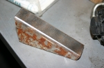 | January 28, 2009 - That 1x3 steel (actually, I think it's 1x2 when I think about it) I used for the steering rack mounts is not new steel.
Far from it - I have some very heavily overbuilt railings that were pulled out of a building under renovation. They live out in the backyard and I chop off a bit when I need it. A bit of quality time under the wire wheel on the grinder and it looks new and ready to weld.
entry 158 - tags: tips | | | 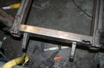 | February 1, 2009 - Time to mount the steering rack, umm, mounts.
I'm still just tacking everything in place, but it's almost time to commit. I did chop a bit of extra frame rail off the sides to clear the rack itself, this was always part of the plan - I figured it was much easier to make them shorter than longer.
entry 159 - tags: steering, frame | | | 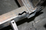 | February 1, 2009 - This cut in the steering crossmember was required to clear the pinion housing on the rack.
It's a bit ugly, these were the chops made to get the clearance I needed.
entry 160 - tags: steering, frame | | | 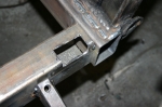 | February 1, 2009 - Once the final clearance was sorted out, I squared off the cut.
Chop chop!
entry 161 - tags: steering, frame | | | 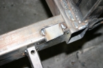 | February 1, 2009 - A small piece of steel was welded in to close up the cut.
It's actually a spare piece of frame rail, the sizing was perfect. Voila, clearance! Once it's welded in completely, I'll clean up the edges with a grinder so it sits flush with the rail.
The steering crossmember could have been smaller, but I wanted the 2x3 tube to give me lots of twisting stiffness for the front of the frame (more than I'd get with a round tube) and to give me a nice flat surface to weld bracing to. Ideally, it should have been 2x2 for packaging purposes so I wouldn't have to do things like this. But that's okay, I think this will end up better overall.
entry 162 - tags: steering, frame | | | 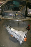 | February 1, 2009 - I borrowed a T56 for some test fitting.
It's a brand new shiny one that should be identical to mine other than the aftermarket shifter. Oh, and a decade of grime! I'm keeping the Camaro together as long as possible.
It's a big boy and weighs about 140 lbs. Quite a contrast from the stock unit, and I'm a bit concerned about fit. But I have a welder!
entry 163 - tags: transmission, Camaro | | | 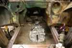 | February 1, 2009 - Here's the transmission sitting in the correct location.
Correct in two dimensions, anyhow. I pulled the bellhousing off because it's much easier to bolt that part to the engine for clearance testing.
Some quick tape measure work tells me that the T56 should fit much, much better than I'd feared. I haven't lifted it up into the car yet (I need to work out a stable way to support it while being able to lift and move it around), but it appears that it should fit into the stock tunnel as if the car was shrinkwrapped around it. Amazing. There's even a crossmember that I think is in the perfect place to support the rear.
entry 164 - tags: transmission, fitment | | | 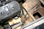 | February 1, 2009 - The plastic engine is back in the car.
I clamped a piece of plywood to the bottom of the framerails to ensure the bottom of the engine will not protrude below. And it's looking pretty good. It needs to come back 1.5" from the current position to put the shifter in the correct location, which will place the right head almost up against the leading edge of the footwell. I can make a little more room there if need be.
On the driver's side, the head sits slightly forward so there's more clearance there. But it does hit this protrusion at the bottom of the footwell. A bit of poking around revealed an odd thing - there's a significant amount of footwell in front of the gas pedal at WOT. Space you simply can't use. Is it left over from RHD versions of the car? That useless space is exactly where I need more room in the engine bay, so this is working out nicely. So nicely, in fact, that it appears very little work will be needed to stuff this giant drivetrain in place. Work beyond rebuilding the frame from the firewall forward, of course. But passenger compartment intrusion will be minimized. Amazing.
entry 165 - tags: footwell, clearance, engine | | | 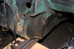 | February 2, 2009 - Time to get out the sawzall, let's get the engine fitted.
This is the passenger's side footwell. This big handy dent is almost perfect. In fact, on initial test-fitting, this side of the car appears to have been factory modified for my needs.
entry 166 - tags: firewall, fitment | | | 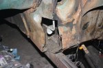 | February 2, 2009 - The driver's side is not as good.
Notice how much further the footwell extends inboard from the frame rail. But all of this space is useless - the gas pedal visible in the cut is at full throttle. So, I shall reclaim this space from the interior for the engine.
entry 167 - tags: firewall, fitment | | | 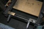 | February 2, 2009 - Remember the steering crossmember that really should have been 2x2?
Well, it's getting closer. To ensure as much oil pan clearance as possible, I had to take a chunk out. Right about an inch at the back and nothing at the front.
entry 168 - tags: steering, frame, clearance | | | 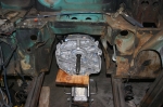 | February 2, 2009 - After a bit of finagling, the transmission is in place.
Sort of. It's sitting about 1" to 1.5" too low and pressed up against the top of the transmission tunnel. Some more surgery may be required - but the fact that I'm this close without making any modifications is astounding. There's one doodad just below the shifter (pardon the technical terminology) that will require a small hammered dent in the tunnel to allow the shifter to be centered in the hole.
However, a test fit of the hood with the engine in place tells me that I'm either going to have to modify the hood or lower the engine. I've been testing the fit with the oil pan level with the frame rails, 5" off the ground. Possibly more, actually, when I review my notes. They show the rails at 5.75" high, although I think that was with the original wheel size. Regardless, I have lots of clearance. I'm tempted to drop the whole thing by 1" to improve clearances everywhere. I'd put a crossmember in front of the pan to protect it. A quick check with a tape measure shows 4" of clearance on one of the Miatas in the garage, so 4" is certainly streetable.
entry 169 - tags: fitment, transmission | | | 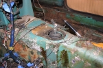 | February 2, 2009 - Here's the current shifter location.
It's offset slightly to one side due to the aforementioned doodad but the longitudinal placement is pretty much perfect.
entry 170 - tags: transmission, fitment | | | 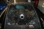 | February 6, 2009 - It's in!
The entire drivetrain is in place. There are jacks and clamps and various cheating involved, but I've found my final location. The engine is down not quite an inch from where I had it before, mostly to accommodate the transmission and tunnel. The problem I had with the hood not closing before? It was the hood prop hitting the top of one of my new suspension towers - you can see how it's been cut down on the right side compared to the left. But still, it makes for a better location.
entry 171 - tags: fitment | | | 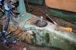 | February 6, 2009 - And here's the final shifter location.
Looks perfect. You can see the square hole I had to cut in the top of the transmission tunnel to make space for the trans - the tunnel has a low point while the transmission does not. Sorry, make that the tunnel had a low point...
The "doodad" I mentioned before is a reverse lockout solenoid. Above 5 mph, the solenoid prevents you from hitting reverse. There's some logic to that, but it's a hassle for me. It could easily be removed completely but given the tight shift pattern of a T56, that's not the most intelligent solution.
On Elvis, we pulled the solenoid out and tweaked the spring tension in the lockout. This negated the need to run wires to the solenoid, but it still left things a bit on the bulky side for me. I'm going to see if I can manage to design a replacement that fits flush to the side of the transmission. It looks plausible.
entry 172 - tags: transmission, fitment, reverse | | | 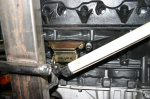 | February 8, 2009 - A view of the driver's side motor mount.
Yeah, it's close to the steering column. I might be able to make it work with some artfully curled tubes - or I'm wondering if I can use the extra pair of bosses on the block and support this side of the engine a bit further back.
I did what is hopefully the final cutting of the tunnel today and welded the frame rails in fully. It's not easy welding 1/8" steel to thin floorboards from below without burning through. It's not pretty work, but it'll hold.
entry 173 - tags: mounts, fitment | | |
|

 THE DIARY