| THE MG |
|
|
 | | 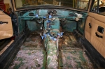 | January 1, 2009 - Naked MG!
Janel and I attacked the car this afternoon and stripped it right down. Now that this is done, it's time to start the real modification. We did discover that while many of the panels in the car were painted, the seat upholstery was not. So it looks as if we do have a color match to an MG color. Based on the catalogs, I'm guessing "honey tan". We'll probably duplicate a couple of the panels if we can find some vinyl, as a few are a bit banged up.
The size of the fasteners holding the seats down was a little spooky - they're about 1/3 the size of the ones used in a Miata.
entry 119 - tags: interior | | | 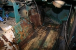 | January 1, 2009 - Now, the big question.
How's the rust? Despite the appearance in this picture, it's actually looking really good. You're looking at some of the carpet underpad stuck to the floor, for one thing.
There was some surface crust on the transmission tunnel on the passenger's side - displayed here - that I suspect was related to the AC. But all that metal will likely be replaced anyhow, and it showed no signs of weakness under a screwdriver attack.
The side sills also look solid under the vinyl cover on first inspection. I'll hit them with a Scotchbrite wheel and make sure. The floorboards have an asphalt matting on them from the factory that could hide any sins, but it's not showing any sort of cracking or distress that I associate with the eruption of rust underneath. A good inspection from under the car confirms this.
I think this car is as solid as it appears.
entry 120 - tags: rust | | | January 1, 2009 - I drove the Camaro just a bit over the holidays.
I also managed to get it stranded at work during a good snowstorm. Dunlop D60 A2s aren't great snow tires. But it's been useful.
First off, I can't wait to liberate this engine from the Camaro. Let's just say that I'm not enamored with the chassis.
Secondly, it's allowed me to identify a couple of little problems. The shifter needs adjusting, I know that. But there was a check engine light on. A bit of monitoring with an OBD-II scanner tells me that the coolant temperature sensor is reading a constant -58F, which I'm pretty sure is not accurate. I suspect that's a "no signal" reading. I'll probably deal with that when the engine is out of the car.
entry 121 - tags: camaro | | | 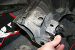 | January 3, 2009 - Now that I've figured out how I'm going to deal with the front suspension, it's time to get cracking.
Lots of measuring and calculating and general head-scratching, and it culminated in this. The donation of control arm brackets (with alignment capabilities) by a stock Miata subframe. The sawzall got a real workout today. That's foreshadowing!
entry 122 - tags: suspension | | | 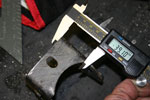 | January 3, 2009 - I've decided the best way to run the rails is just inboard of the stock ones.
That'll let me run them back to the middle of the car (where the stock ones stop) and tie them in together. More strength for the car!
This puts the outside edges of the rails 570 mm apart. To put the brackets in the correct place, they need to be 38.5mm at this dimension. Not bad for cutting with a relatively blunt instrument, no? I'll clean them up a bit on a belt sander before welding. The dimension isn't critical to the half millimeter (0.020" for those who speak the old language) because there's a significant amount of adjustment room in the control arms - but it's good to be fairly accurate here if possible. I'd hate to run out of adjustment for the alignment.
entry 123 - tags: suspension | | | 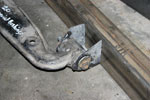 | January 3, 2009 - A view of the bracket on the new frame rail.
The new rails are 2x3" 18 gauge, which is significantly bigger than the stock stuff. Fair enough, there's a lot more running through them! I'll have lateral bracing wherever I can fit it, as well as a bit of vertical to stiffen things up.
After much measuring and poking around and measuring, it turns out that the correct height for the control arms is serendipitously right in the middle of the frame rail. I played around with heights ranging up and down a couple of inches, and this puts them 7" from ground level. That's 1" higher than the ones on Janel's slightly lowered Miata, making the geometry just about a perfect match for a stock Miata.
entry 124 - tags: suspension, ride height | | | 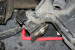 | January 3, 2009 - The brackets for the front control arm pivot point aren't as conveniently designed to be cut off as the rears are, and the bushing is wider.
So I took a rear one and cut it in half. Yes, I'll need another Miata subframe to supply me with enough raw material, but that's not a big problem for me.
entry 125 - tags: suspension | | | 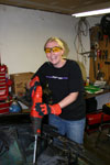 | January 3, 2009 - Janel wandered into the garage and immediately got bored with all of my careful measuring and figuring.
She was not thrilled by my demonstration on how the control arm would mount to the frame rail. She wanted to see big dramatic changes.
So I handed her the sawzall.
entry 126 - tags: destruction, Janel | | | 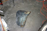 | January 3, 2009 - And out comes part of the engine bay.
We cut the frame rail off at the firewall and again at the factory radiator support. A big chunk of inner fender was removed as well. More will come out later, but this is a good start. And it was dramatic enough to keep Janel happy.
entry 127 - tags: destruction, frame | | | 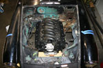 | January 3, 2009 - With the frame rails out of the way, we did an engine test fit.
It's the first time I've dropped the engine in with a throttle body. And this is pretty much the correct location for it. I just need to check my driveshaft angle and I think it'll move back approximately an inch, but everything works well. The shifter comes out in the stock position and most of the engine is behind the wheel line - marked here with blue tape.
entry 128 - tags: engine, fitment | | | 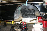 | January 3, 2009 - Here's a view of the engine height.
At my planned ride height, I'll have about 5" of air under the bottom of the pan. It's only going to protrude about 3/4" below the stock frame rails. More importantly, I'll also have it nicely protected. And you can't see it in this picture, but the hood is on and latched!
It'll fit without body modifications!
entry 129 - tags: engine, fitment | | | 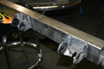 | January 4, 2009 - Now I feel like I'm making some progress.
It's no world-changing piece of fabrication, but the lower control arm mounting points are in place on one of the frame rails. This is the first constructive step of the project, everything else has either been preparation or destruction. A few more of these sorts of changes and the car will be ready to drive!
entry 130 - tags: suspension | | | 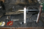 | January 9, 2009 - Time to build the brackets for the upper control arm.
Step one, get my hands on a front subframe that doesn't have the rear mounts hacked off. Oops! Luckily, there was one in the metal dumpster at Flyin' Miata.
Step two, build a jig to locate the upper control arm mounting points in space. This isn't exactly a production quality jig, but it'll do for a one-off. It's accurate, which I tested by removing and replacing the stock piece a few times. A couple more pieces were added after this picture was taken, but you get the idea.
entry 131 - tags: suspension, frame, jig | | | 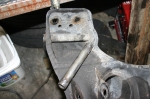 | January 9, 2009 - The upper arm is bolted onto this tube.
It's a metric size, and there's nothing quite right available off the rack. I don't want any slop in the long bolt that runs through the tube for obvious reasons.
So I went back to the sacrificial subframe and chopped one out. Here you see the before and after. There's an amazing amount of weld on this tube, there was lots of grinding involved.
entry 132 - tags: subframe, suspension | | | 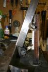 | January 9, 2009 - Here's a rough approximation of how the upper mount will be supported.
A section of the same 2"x3" square tube that makes up the chassis rails will go up and out, and extend beyond the upper arm mounting to provide the upper shock mounting location. Some fore/aft bracing will be added later, and I'll run something from side to side at the top if the engine allows. The base of the bar will also move closer to the center of the frame rail, this is mostly just a convenient place to sit it right now.
I could mount the bar like this, with the upper arm mounting tube welded to the side of the bar. That gives a slightly better location for the shock mount.
Another option would be to angle the bar more and run the tube through the center of the bar. That would be stronger for the tube, but less ideal for the shock mount. Since the shock mount is going to get big loads (the vertical loads from the car go through it while the upper arm mostly has to deal with some side loads and a forward load on braking), I'm thinking the first option might work better.
I'm starting to wonder if I'm going the wrong way here. Should I have the frame rails kick upwards after the firewall, supporting the lower control arm mounting points with a crossmember that dips down under the engine? I'm worried about twisting loads coming from that upper shock mount located so far away from the rail. I could tie into the body, but there's not really much there. Then again, the Miata doesn't have a whole lot of metal in that area and there are no side loads on the shock due to the double wishbone configuration. Meanwhile, the lower control arms take the brunt of the cornering loads from what I understand. Hmm.
entry 133 - tags: suspension, frame | | | January 9, 2009 - While looking around to examine various frame designs, I came across this ambitious project.
A Miata stuffed inside an Morris Minor. I've seen it in the past but had forgotten about it. And check it out, there's the same suspension setup I'm working on. No pictures of the final product which is a shame, but there are some good ideas in there. I like the wood mockup.
entry 134 - tags: suspension, frame | | | January 10, 2009 - Okay, I think I have it.
The crossmember to mount the steering rack actually has to go directly in line with the front lower control arm mounts. I can use a plate or some bars to triangulate the upper mount points to this, getting rid of my twisting problem. It's still a ladder frame with the torsion problems that implies, but a full space frame isn't going to happen at the front of this car.
I'm going to keep thinking about this, both how to implement with the lower control arms as-is and how to deal with the upper location, but I think I'm on the right track.
entry 135 - tags: suspension, frame | | | 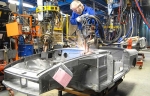 | January 11, 2009 - Ooo, a naked MG!
This is from the very cool British Heritage website. From this and other pictures, I have a better idea of where the various beams and strong points are to be found in the body shell. For example, there's a beam at the top of the fender that I'd never noticed before.
I'm going to triangulate my suspension pickups off them, making a pseudo-spaceframe out of the front end. I have a number of the new tubes figured out, but I won't sort out their final locations until the engine is in place. I suspect a few of them will have to be removable as well to deal with engine serviceability.
One thing that occurred to me yesterday is that the high frame rails with a dropped crossmember for mounting the lower control arms won't work with Miata geometry. The front and rear pickup points are a long way apart, and the crossmember for the rear one would go right through the oil pan. That's not good.
entry 136 - tags: suspension, frame | | | 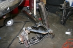 | January 11, 2009 - It doesn't look like much after all that work.
Still, here's the first corner of the new frame. When I look at it in the car, I realize how short many of these distances really are. Most of the length of this bar will be welded to the bottom of the car, both to the floorboard and tied into the existing frame rail. It's not going to be difficult to make everything stiff and solid. I spent most of my working time today finishing some of the design work in my head, and I'm pretty happy with it all. This is just a skeleton.
You can barely see it in the picture, but the upright is welded to the front suspension pickup. I'll add in an extra triangle to help spread the forces around as well as tie into the crossmember that will support the steering rack. The upper end will be tied into the top of the fender and the beam in there, as well as back to the firewall on a bit of an angle. I'm also planning a little more bracing to tie the upper control arm mount to the upright a bit more - nothing complex.
The one mistake I made was that I didn't cap off the end of the upright, and it's going to be tough to do now. I don't really want to leave it open to the elements either. Whoops. It's possible to do, but it will be awkward. Then again, there's no chance of water getting trapped in there now! Is it better to make it watertight (hopefully!) or to make it irrelevant if water gets inside?
entry 137 - tags: suspension, frame | | | 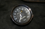 | January 14, 2009 - I picked up a spare speedometer on eBay.
The plan is to stuff electronic guts inside the stock gauge, and I figured having an extra would make me more comfortable taking it apart. I'd rather not go to a $300 adapter or use Autometer gauges, I like the old Smiths look. Besides, it was cheap!
entry 138 - tags: interior, gauges | | |
|

 THE DIARY