| THE MG |
|
|
 | |  | November 4, 2009 - All attached!
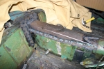
The bracket was welded in, then the tunnel reinforcement was welded to the bracket and then to the tunnel. I was simply going to stitch weld this into place, but, well, I got a little carried away. I'm not worried about this coming apart, I think the whole car will be stronger for it.
entry 203 - tags: suspension, bracing | | | 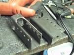 | November 7, 2009 - After a certain amount of noise in the garage, I've finished the axle brackets for the lower trailing arms.
I gave my self multiple holes so I can play the geometry, but the second from the bottom is the one I'm planning to use.
Things are starting to come together on the suspension setup. The MG had a travel limiting strap, and the mounting bracket is well placed for the shock mounting and I can put the shock mount on the back of the lower trailing arm brackets. I'm not sure the upper will be strong enough so I'll probably reinforce the bracket. All this will give me enough room to comfortably run a shock with 5" of travel.
I'm also going to use the bumpstop mounted on the frame so I don't rely on the bumpstops on the shock, which will also take some hard impact loads off that bracket. It does mean I'll have a hard rubber bumpstop, and I'd prefer a softer setup. But I'll see what I can do about that down the road.
So, plan of attack. Build the mounting bracket for the upper link, then weld all the various brackets on the axle. That'll be fun - the center one will be welded to cast iron, which is not something I've done before. I also have to be careful not to warp the axle housing with the two lower brackets. Once I have the brackets on, I'll confirm the length of the arms and order the swaged tubes for the arms. Then I'll be able to move the suspension through its range of travel and figure out the best way to run the Panhard rod.
entry 204 - tags: suspension | | | 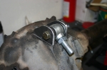 | November 10, 2009 - The bracket for the center link has been fabricated.
Now I just need to stick this thing on there. The housing is nodular iron, a sort of cast iron that's more ductile than the really cheap stuff. Much easier to weld from what I understand, but it still takes more effort than just hitting it with the MIG.
From what my research tells me, the easiest way to weld it is with a stick welder. I don't know how to stick weld (yet) but my friend Brandon is willing to help out. I picked up some nickel rod today for the job. It's also important to minimize the thermal shock to avoid cracking. We'll pre-heat the housing with a torch before welding and use the torch to keep it hot after the bead is laid down. We'll see how this works.
I also finished a bit of welding on the center bracket on the body. It's not all that pretty, but it will do the job. That puppy is not coming out!
entry 205 - tags: suspension | | | 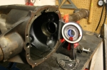 | November 12, 2009 - Time to weld the brackets for the lower arms to the axle housing.
Of course, the housing is round and there are many ways I could stick the parts on them crooked. The back of the differential housing is perpendicular to the pinion, so I set that up to be vertical. A Miata jack under the nose of the housing let me finely adjust the angle. The arms were also set up to be level.
After all that welding in and under the car, having the pieces sitting in front of me on my solid workbench is a real luxury!
entry 206 - tags: suspension, rear axle | | | 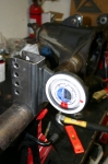 | November 12, 2009 - With the housing properly located, I did a bit of final fitting.
The brackets need to be 905mm apart on the inside edge and vertical in two planes. A bit of careful work, some solid tack welds and voila!
Except I made a mistake. The brackets on the chassis aren't designed to use washers. These are, and I forgot to take the thickness of the washers into account. They're right around 3/32" thick, so I have the brackets 3/16" too far apart. Argh. Is that enough to be a problem? Will I have to cut the brackets off and move them? I don't know. I'll get the tubes and test fit, and see if there's any sign of binding. I have a couple of ideas that don't involve the grinder, but that really would be the smart solution.
entry 207 - tags: suspension, rear axle | | | 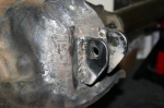 | November 17, 2009 - Thanks to Brandon, the brackets are welded on the top of the diff.
I ran the torch, heating the whole area up to about 700F. Once the heat had stabilized, Brandon stick-welded the brackets on with a nickel rod as I continued to play the torch around and keep things warm. Once the welding was done, I continued to heat the differential and gradually brought the heat down. Once we got it down to about 450F, we wrapped the whole thing in a welding blanket and let it cool gradually overnight. The end result? No cracks!
Brandon would probably like me to mention that it's a bit out of practice, but the welds are strong. I tested them by beating on them with a hammer.
entry 208 - tags: rear axle | | | November 17, 2009 - Of course, after all that measuring and checking, one of the lower brackets was a bit crooked.
I'd been quite careful to align everything, but one must have shifted as I tacked it on. It was about 1.5 degrees off where it should be, but was visibly crooked. The human eye is unforgiving!
It didn't take long to cut it off (that's why they were only tacked on securely instead of having the full bead applied) and reposition it. So there's that solved.
Once that was done, I slid the axle under the car and supported it on jackstands at the normal ride height. I then measured the exact distances from the brackets to the chassis so I could order the right parts from Speedway Motors - some swaged steel tubes with both left and right hand threads so that adjusting is a snap. Besides, the tubes are the same price as one weld-in bung for making your own! I did pick up a couple of those so that I could make my own Panhard bar, though. It'll be longer than the tube lengths, and this way I can use a larger diameter tube for more stiffness over the longer length. I'm going to make it as long as I can to minimize lateral movement of the axle through the suspension travel. Anyhow, I should hopefully have those parts on Friday so I can actually attach the axle to the car! At which point I will undoubtedly discover something terrible.
I also measured my planned shock mounting point. Hmm. If I want to use that location and retain a shock of any significant travel, I'll have to extend my lower brackets down further. This will put the bottom of the shock about 4" from the ground. Not really a problem of course. I do have room to put the shock in the wheelwell with my current axle, but that may limit my options for more tire in the future - I'm considering narrowing the rear so I can run wider rubber. If I do extend the lower brackets, I can either weld an extension on to the existing ones or chop them off and build another set that's longer. I'd probably go with the latter, it's the smart way to go.
One piece of good news - looks as if there's enough room for the Panhard rod behind the axle. Excellent. This means it can be straight instead of having to bend where it goes over the diff, and thus will be stronger.
entry 209 - tags: suspension | | | 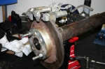 | November 17, 2009 - So, while I wait for suspension parts to arrive, time to look at the brakes.
I'll be mounting a set of Miata rear calipers and discs. I hadn't really thought too carefully about how to do this before, but I could have started as soon as the new axles arrived. As it turns out, it's going to be fairly straightforward.
entry 210 - tags: brakes | | | 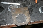 | November 17, 2009 - The beginnings of a rear brake bracket.
Most of my axle uses 2.625" tubing, and it's impossible to find a 2.625" hole saw. This meant lots of grinding for my trailing arm brackets. Are they trailing arms or radius rods? I'm not really sure. Anyhow...
A look at the end of the axle tube revealed that there's a step in the tube size, dropping down to 2.5". That size hole saw I have! And with the axle removed, I can slide my bracket right over the end of the axle tube so I can get a full 360 degree weld. Excellent. The bracket is made of 0.25" steel, nice and beefy. The two mounting points for the caliper are in the same plane, so all I need to do is drill two holes in the right place and weld this on.
Well, almost. Naturally, the bracket uses 10mm metric bolts. I have a 0.375" drill, but 10mm is 0.394". I'd rather not go oversize (7/16 is 0.438") so I'll have to see what my options are for opening up the hole slightly.
The bracket also ends up very close to the end of the tube, so I'm going to put a 0.25" spacer to move it inboard a bit and get more room for welding. That'll also give the mounting bolts for the caliper a bit more meat around them to help them resist shear.
It's kind of funny - I've taken the Seven to two magazine tests over the years. One was in the company of a bunch of other Locosts, the other was to compare against a $75,000 supercharged Atom. In both cases, I was called "a ringer" because of my purported access to equipment and tools not available to mere mortals. Want to know what I've been using for all of my recent fabrication? The holy trinity of a good drill, a sawzall and an angle grinder. Yes, a MIG welder, stick welder and a torch have also recently come in to play, but they're not exactly unusual tools for fabricators. I don't even have a bandsaw. The car is on jackstands in my garage, a far cry from the bead-blasted perfect shell on a rotisserie that some people might expect.
My point here is not to say "oh, poor me", but to point out that you really don't need a lot of equipment to do this kind of work. This bracket isn't as pretty as it might be, but a bit more time with the grinder will fix that.
entry 211 - tags: brakes | | | 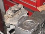 | November 19, 2009 - The brake brackets are ready to weld on to the axle tube.
I'd been trying to figure out the best way to ensure the holes were in juuust the right place. I needed to get the radial location of the caliper just right. Measuring wasn't going to work well as I was dealing with curved surfaces everywhere. After a bit of cogitating, I came up with a cunning plan. Naturally, I wasn't bright enough to take pictures of the process, so I'll have to try to explain.
First, I used a transfer punch to mark the center of the two holes in a piece of 1"x0.25" strap. This is my 0.25" spacer. I drilled those out (I found a step drill that was close enough to 10mm to solve my previous problems) and checked that they were accurate on the caliper.
I then took a couple of bolts and cut them down into short studs, which protruded out of the caliper by 0.25". This way I could hang the spacer on them and butt it up flush against the face of the large bracket piece.
Now the axle and brake rotor were mounted to the rear end. I placed the caliper in the perfect location and held it in place by tightening down the adjuster screw Mazda thoughtfully provided, clamping the caliper in the right spot. Now it was a matter of assembling all of my pieces - the bracket on the axle (loose) and the spacer hung on the caliper. I lined everything up and tack-welded the spacer to the bracket. Now, I had my holes lined up! I drilled the rest of the bracket to match, welded it up and voila.
The second was easier. Now that I had one accurate bracket, I used the transfer punch (wonderful things, these are) to put the holes in the same place and stuck it all together.
Now all I have to do is figure out just how I want to clock the calipers on the axle. I'll mount the rear end to the car and find out if there are any potential interference points with the body.
entry 212 - tags: brakes, rear axle | | | 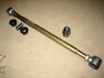 | November 19, 2009 - A big box full of MG suspension parts arrived in the mail!
Well, I know they're MG suspension parts. Most people probably wouldn't identify them as such.
A collection of swedged rods for my trailing arms along with 4 left-hand thread ends. I'm sure I ordered the latter back in the summer, but they're nowhere to be found. At worst, I have some spares.
I also picked up a couple of weld-in bungs so I can build the Panhard bar. I'm pretty close to that point. Cool.
entry 213 - tags: rear axle, suspension | | | 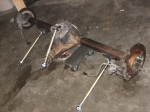 | November 20, 2009 - Time to assemble the rear and attach it to the car!
First off, with the differential, axles, brakes and trailing arms attached, it's really heavy. Yowza. Lifting this thing off the workbench was an excellent illustration of unsprung weight.
entry 214 - tags: rear axle | | | 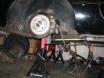 | November 20, 2009 - The axle in its new home!
It took a bit of fiddling around with trailing arm length to get it in just the right place, and I think I'm going to have to pick up some lower ones that are an inch longer. No worries, they're only about $12 each. I'm actually really liking these, I'm trying to think of other cool places to use them. It's super-easy to adjust the pinion angle and the rear axle angle.
In this picture, I have the jackstands at different heights - the arms are usually parallel! I also took the shot before I went on a major garage cleaning binge. That's how it usually works, right?
entry 215 - tags: rear axle, suspension | | | 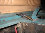 | November 21, 2009 - With the axle actually attached to the car, I was able to move it through the full range of motion.
As I suspected, at full compression the upper link hit the bottom of the car. After a bit of fine metalwork, I had that problem solved! Right now, maximum compression is actually a bit more than was available on the original suspension. My tires are a smaller overall diameter but since they're further outboard, getting this much travel is going to involve quite a bit of surgery to the wheel wells before the fender flares go on. The plan to to build the car to allow this much travel, then use spacers to limit it to less if that should become necessary for any reason.
It was very cool to be able to put the axle through its paces and see how things worked, then simply reach up and tweak the pinion angle or the fore-aft location.
entry 216 - tags: rear axle, suspension, travel | | | 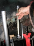 | November 21, 2009 - I'm still playing around with places to put the coilovers.
This rod is the same length as a fully compressed AFCO shock with 5" of travel. With the suspension at full compression, it helps me determine my worst-case scenario for mounting points. I'm starting to lean towards putting the shock in the wheel well. It'll take up a bit of space that could be used for tire, but on this axle there aren't really any options for moving the tire inboard much anyhow. As long as I have an inch or two of clearance, it shouldn't cause any real problems.
If I do decide to narrow the rear axle to allow more tire - since this is a street car, not a drag or track car, I don't need monster rubber - I can always move the shock. The good thing about this setup is that I'll have more ground clearance and I'll have a much easier time welding in a strong upper mount for the shock than if I tried to use the mount for the travel limiting strap.
entry 217 - tags: suspension, rear axle | | | November 24, 2009 - There won't be much work done on the car over the long weekend - my parents are coming to visit.
Thus the massive and long overdue garage cleanup!
Still, I'm spending a lot of time designing things in my head. Next is the Panhard bar. Ahead or behind the axle? I also spent some time designing the front end bracing in my head on the way to work this morning. I really enjoy the process of working through problems mentally.
entry 218 | | | November 30, 2009 - The weekend wasn't completely without progress.
I got all itchy to do something productive so I figured out how to mount the Panhard bar and also welded the brake brackets on to the axle. One step closer. I'll do the messy fabrication work for the bar this week and get it all put together.
I also took advantage of a Black Friday sale at Discount Tire Direct and picked up some new tires for the car. The eventual plan will probably involve some 15x8 wheels in the rear with 225/45-15 tires, but I'll probably have to shorten the rear axle to do that. For the initial build, I'll stick with my current setup of 14" wheels with 195/60-14 tires. Yes, miniscule by modern standards and the skinniest tires on any vehicle I own when I think about it. But I have the wheels, they look appropriate on the car and I have the wheels. The tires are a set of Falken Azenis RT-615s, and I got the full set for $176 delivered. Can't beat that for value. They might be small, but they're pretty sticky for a street tire.
I also just ordered the shocks. Things are moving along. I'm thinking the Christmas holiday will involve the dissection of a certain Camaro.
entry 219 - tags: rear axle, suspension, tires | | | 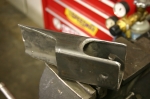 | December 1, 2009 - Panhard rod mount!
As I've mentioned, I'm using the Fast Cars suspension as a base for my design - albeit with a bit more adjustability built in. In that case, the Panhard bar mount is in front of the axle. This means it has to be fairly tall, and it has some support braces to keep it from flexing under side loads. The roll center of the rear axle is the center of the Panhard bar, and the usual geometry means the bar should be in line with the center of the axle at ride height. Thus the long bracket design.
I've decided to put mine behind the axle. This lets me use a straight bar instead of having a bend to clear the nose of the differential. It also means I can take advantage of the contours of the body and use a much shorter mount. It's also a bit of an odd shape and will have a very solid connection to the body of the car. It's made of 2x3 tube instead of the 2x2 in the Fast Car setup and the extra width is in the right place to resist lateral loads. It should be significantly stronger but there's not much clearance for the bar. I think I'll be able to pull it off though.
I should have this welded in to place shortly, I just have to pull out a bit of carpeting inside the car so nothing catches on fire. You know, the usual.
While underneath working this out, I think I figured out how to mount a sway bar to the rear. Hmm.
entry 220 - tags: rear axle, panhard, suspension | | | 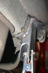 | December 2, 2009 - The Panhard bar mount welded in place.
This is one solid sucker, I'm very happy about that. The bend in the body makes it good and strong.
entry 221 - tags: panhard, rear axle, suspension | | | 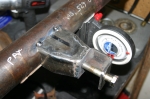 | December 2, 2009 - With the body mount in place, it's time to build the one on the axle.
I welded one of the threaded bungs into a length of 1" pipe and attached it to the body. Then the axle got put into place and I measured the distance from the bar to the axle. That gave me what I needed to figure out what the mount on the axle should look like.
I went through a number of possible designs for this. The final one - shown - has a bracket made of a section of 2x2 bar with a nice thick wall. It's welded to a support made of 2x3 bar, reshaped to meet up. There's a nut welded on the back side of the bracket. A lot of designs I see in circle track catalogs put the bolt in single shear instead of double like this, but I prefer this design.
entry 222 - tags: rear axle, panhard, suspension | | |
|

 THE DIARY
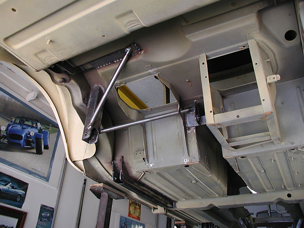