| THE MG |
|
|
 | | June 30, 2009 - Oops.
I decided to install the axles in the differential last night. Imagine my surprise when it became obvious they just weren't going to fit. The inner end of the axles was about 0.035" too long, preventing me from assembling everything. That's a bit frustrating.
An email to Moser and the current theory is that my axles were made with a "button" intended for an 8.5" differential. Mine's a 7.625" setup. So they're going to make another set and I'll return these. Good thing I didn't press all the studs into the flange yet!
entry 192 - tags: rear axle | | | July 25, 2009 - Janel and I took a bit of a break and headed off on a trip for a while.
Three weeks away is great for clearing the head. Plus, it meant that there were a new set of Moser axles waiting for me upon my return.
But I have a problem. Part of the error in the original Moser axles was a C clip groove that was 0.025" too large in diameter. So I had to tap the clips into place. If I had more experience with these sorts of axles, that should have been a danger sign. The result is that I simply can't get the clip off one of the axles. It's the side with the ring gear, which is blocking my access somewhat.
I've been fighting this for a while. Right now, it looks as if the best option will be destructive removal of the clip, and the best suggestion I've heard for that is freezing with liquid nitrogen and then employing a short, sharp shock with a chisel. Cutting doesn't look plausible due to access problems. I'll cut the axle in half if I have to, but I have to figure out how to get in there to do the cutting.
The good news is that the only part of this whole assembly I really need to keep is the housing. If I have to cut the differential apart, so be it.
I also learned yesterday that Z28 Camaros have a Torsen differential. Excellent. No, wait, that's 1999-02 Z28s. Our donor is a 1998. I think that means we have a Positraction. I'm trying to learn more about that now.
entry 193 - tags: rear axle | | | July 26, 2009 - I win!
I always win. It's just a matter of how much the car has to suffer, really.
I asked the creative minds on the Grassroots Motorsports forum for suggestions. While I initially homed in on the liquid nitrogen option, one comment stuck with me. Drill a hole for a screw and pull it out. But if I can drill a hole for a screw, what if I drill a larger hole and cut the C clip in half?
I didn't quite manage to break it in half, but I weakened it enough that I was able to spread the clip apart and remove it. Voila, the axle has gained its freedom!
Unfortunately, that's liable to be the end of any work on the MG for some time. I'm working on a new book and it's late. Very late. My editor has run out of smiles, so all my free time for the next few months will be spent putting words together. The MG will resume once I have also gained my freedom.
entry 194 - tags: rear axle | | | 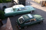 | August 18, 2009 - We have a new car!
In part exchange for some work I did on an MG Midget a few months back, this 1969 GT got dropped off. It's a parts car with no engine or brakes, and I was expecting a real wreck. It's actually not all that bad! A few bubbles on the sills, as one might expect, but no gaping holes. The paint looks as if it may have been applied with a brush, but at least someone took the trim off first. The grille is pretty good, bumpers are solid, the dash looks good - overall, it's salvagable. I even have a title.
I'm almost going to feel bad using this as a parts car. Let's see how many parts I actually need first.
entry 195 - tags: parts car | | | 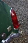 | August 18, 2009 - The parts car came with the older style taillights.
A number of people have commented how they like these better than the chunkier ones on our 1972. I may swap them out. It's an interesting option. The parts car is missing the upper section of one light, but Moss has those for $17.30.
entry 196 - tags: parts car, taillights | | | 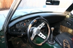 | August 18, 2009 - The interior of the parts car isn't exactly pristine, but the dash is in better shape than the 1972 one.
It's a pillow dash without a glovebox, but the switchgear is in much better shape and the instruments look really good. Excellent source for restoration parts. Plus it comes with a "Personal" steering wheel!
I love the wood trim on the bottom of the doors. That's actual wood paneling.
entry 197 - tags: parts car, dash | | | 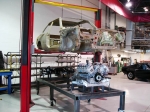 | August 18, 2009 - Now here's the right way to do a major swap.
This poor BMW M3 got stuffed full of all sorts of late-model parts. It's a real sleeper and the pictures of the full build are worth a close look. Beautiful work.
What really impressed me was how it was done. Check out that big solid build table. It's flat, straight and level. The front and rear subframes were bolted to extensions on that table to ensure they were perfectly positioned. Then the various frame parts needed to keep them together were welded up, and the car was built up from there. Even the exhaust system used the build table for alignment.
That's how to do it right. None of this "cut the frame rails off, build replacements on the table and then weld them in" stuff that hacks like me do in their garage. The fabrication involved is beautiful as well.
I can't wait until I'm done with the book so I can dive back into this car. I'm going to keep going back to these photos for inspiration so that when the time comes, I'll be motivated to do a similar quality job.
The full story of the build from the guys who did it.
entry 198 - tags: other builds | | | 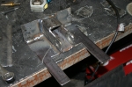 | October 26, 2009 - The book is done, so it's time to tear back into the MG.
Janel's been asking when I'd start working on her car again, and with a day off the answer was "today"! This is the new mounting point for the upper suspension link. I've been basing my design on the Fast Cars three-link used in the well-documented build of Dan Masters' Ford-powered car. I'm not as pretty a fabricator as those guys are, and I was definitely cursing my lack of a bead-blasted and pristine shell today as I cut brackets off around the battery boxes. Yuk.
From what I can figure, this thing will mostly see tension as the diff tries to rotate upwards. The Fast Cars solution includes a reinforcing brace along the top of the transmission tunnel which seems like a pretty good idea. The only downside is that it would require custom carpet, and I'd much rather deal in metal. I'll probably put something similar in and solve that problem later.
entry 199 - tags: suspension | | | 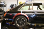 | October 26, 2009 - I stuffed the rear axle under the car and lifted it into place, just to see how everything fits.
This was a reward to myself at the end of the day, so I haven't actually crawled under to discover what's liable to give me fits yet. I know there will be something. I realized today that the battery I was planning to use - a big burly Optima - won't fit in an unmodified battery box. So I'll have to do something clever down there. Anyhow...
The wheels look good! I'm very happy with that. There's loads of room inside, and I'll probably stick a coilover in there so they don't hang down as low as they do on Masters' car. These weedy little 195/60-14 tires will fit quite nicely under the Rabbit flares too. If I do decide to go fatter - say, a 225/45-15 on a 15x8, which would be a very logical thing to do - I'm going to have fender clearance problems. Maybe I'll just use very good tires and acknowledge the car will be woefully under-tired. I should be able to run a 205/50-15 without trouble if I'm clever with my offset choices. Still, these are +45mm wheels. You don't tend to see too many that are higher than that. I could always get the housing and axles shortened if it comes to that. For now, we'll build for a 205 tire.
You can see here how much trimming the stock fender will need here.
entry 200 - tags: wheels, body, tires | | | 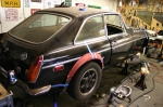 | October 26, 2009 - A 3/4 view of the wheel/tire/fender mockup.
I really like the way this sits. Not so sure about the color scheme though. It's also really tempting to see what I can do about a set of box flares. But that would be anachronistic.
entry 201 - tags: body, wheels | | | 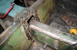 | November 4, 2009 - Time to attach the suspension mount.
I'll weld around the edges as best I can, but I also added holes so I could use rosette welds to attach it to the bulkhead. The rectangular hole - after a bit of cleanup - is where the transmission tunnel brace will go.
Poor MG.
entry 202 - tags: suspension | | | 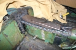 | November 4, 2009 - All attached!
The bracket was welded in, then the tunnel reinforcement was welded to the bracket and then to the tunnel. I was simply going to stitch weld this into place, but, well, I got a little carried away. I'm not worried about this coming apart, I think the whole car will be stronger for it.
entry 203 - tags: suspension, bracing | | | 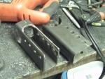 | November 7, 2009 - After a certain amount of noise in the garage, I've finished the axle brackets for the lower trailing arms.
I gave my self multiple holes so I can play the geometry, but the second from the bottom is the one I'm planning to use.
Things are starting to come together on the suspension setup. The MG had a travel limiting strap, and the mounting bracket is well placed for the shock mounting and I can put the shock mount on the back of the lower trailing arm brackets. I'm not sure the upper will be strong enough so I'll probably reinforce the bracket. All this will give me enough room to comfortably run a shock with 5" of travel.
I'm also going to use the bumpstop mounted on the frame so I don't rely on the bumpstops on the shock, which will also take some hard impact loads off that bracket. It does mean I'll have a hard rubber bumpstop, and I'd prefer a softer setup. But I'll see what I can do about that down the road.
So, plan of attack. Build the mounting bracket for the upper link, then weld all the various brackets on the axle. That'll be fun - the center one will be welded to cast iron, which is not something I've done before. I also have to be careful not to warp the axle housing with the two lower brackets. Once I have the brackets on, I'll confirm the length of the arms and order the swaged tubes for the arms. Then I'll be able to move the suspension through its range of travel and figure out the best way to run the Panhard rod.
entry 204 - tags: suspension | | | 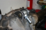 | November 10, 2009 - The bracket for the center link has been fabricated.
Now I just need to stick this thing on there. The housing is nodular iron, a sort of cast iron that's more ductile than the really cheap stuff. Much easier to weld from what I understand, but it still takes more effort than just hitting it with the MIG.
From what my research tells me, the easiest way to weld it is with a stick welder. I don't know how to stick weld (yet) but my friend Brandon is willing to help out. I picked up some nickel rod today for the job. It's also important to minimize the thermal shock to avoid cracking. We'll pre-heat the housing with a torch before welding and use the torch to keep it hot after the bead is laid down. We'll see how this works.
I also finished a bit of welding on the center bracket on the body. It's not all that pretty, but it will do the job. That puppy is not coming out!
entry 205 - tags: suspension | | | 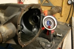 | November 12, 2009 - Time to weld the brackets for the lower arms to the axle housing.
Of course, the housing is round and there are many ways I could stick the parts on them crooked. The back of the differential housing is perpendicular to the pinion, so I set that up to be vertical. A Miata jack under the nose of the housing let me finely adjust the angle. The arms were also set up to be level.
After all that welding in and under the car, having the pieces sitting in front of me on my solid workbench is a real luxury!
entry 206 - tags: suspension, rear axle | | | 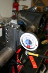 | November 12, 2009 - With the housing properly located, I did a bit of final fitting.
The brackets need to be 905mm apart on the inside edge and vertical in two planes. A bit of careful work, some solid tack welds and voila!
Except I made a mistake. The brackets on the chassis aren't designed to use washers. These are, and I forgot to take the thickness of the washers into account. They're right around 3/32" thick, so I have the brackets 3/16" too far apart. Argh. Is that enough to be a problem? Will I have to cut the brackets off and move them? I don't know. I'll get the tubes and test fit, and see if there's any sign of binding. I have a couple of ideas that don't involve the grinder, but that really would be the smart solution.
entry 207 - tags: suspension, rear axle | | | 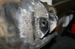 | November 17, 2009 - Thanks to Brandon, the brackets are welded on the top of the diff.
I ran the torch, heating the whole area up to about 700F. Once the heat had stabilized, Brandon stick-welded the brackets on with a nickel rod as I continued to play the torch around and keep things warm. Once the welding was done, I continued to heat the differential and gradually brought the heat down. Once we got it down to about 450F, we wrapped the whole thing in a welding blanket and let it cool gradually overnight. The end result? No cracks!
Brandon would probably like me to mention that it's a bit out of practice, but the welds are strong. I tested them by beating on them with a hammer.
entry 208 - tags: rear axle | | | November 17, 2009 - Of course, after all that measuring and checking, one of the lower brackets was a bit crooked.
I'd been quite careful to align everything, but one must have shifted as I tacked it on. It was about 1.5 degrees off where it should be, but was visibly crooked. The human eye is unforgiving!
It didn't take long to cut it off (that's why they were only tacked on securely instead of having the full bead applied) and reposition it. So there's that solved.
Once that was done, I slid the axle under the car and supported it on jackstands at the normal ride height. I then measured the exact distances from the brackets to the chassis so I could order the right parts from Speedway Motors - some swaged steel tubes with both left and right hand threads so that adjusting is a snap. Besides, the tubes are the same price as one weld-in bung for making your own! I did pick up a couple of those so that I could make my own Panhard bar, though. It'll be longer than the tube lengths, and this way I can use a larger diameter tube for more stiffness over the longer length. I'm going to make it as long as I can to minimize lateral movement of the axle through the suspension travel. Anyhow, I should hopefully have those parts on Friday so I can actually attach the axle to the car! At which point I will undoubtedly discover something terrible.
I also measured my planned shock mounting point. Hmm. If I want to use that location and retain a shock of any significant travel, I'll have to extend my lower brackets down further. This will put the bottom of the shock about 4" from the ground. Not really a problem of course. I do have room to put the shock in the wheelwell with my current axle, but that may limit my options for more tire in the future - I'm considering narrowing the rear so I can run wider rubber. If I do extend the lower brackets, I can either weld an extension on to the existing ones or chop them off and build another set that's longer. I'd probably go with the latter, it's the smart way to go.
One piece of good news - looks as if there's enough room for the Panhard rod behind the axle. Excellent. This means it can be straight instead of having to bend where it goes over the diff, and thus will be stronger.
entry 209 - tags: suspension | | | 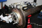 | November 17, 2009 - So, while I wait for suspension parts to arrive, time to look at the brakes.
I'll be mounting a set of Miata rear calipers and discs. I hadn't really thought too carefully about how to do this before, but I could have started as soon as the new axles arrived. As it turns out, it's going to be fairly straightforward.
entry 210 - tags: brakes | | | 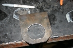 | November 17, 2009 - The beginnings of a rear brake bracket.
Most of my axle uses 2.625" tubing, and it's impossible to find a 2.625" hole saw. This meant lots of grinding for my trailing arm brackets. Are they trailing arms or radius rods? I'm not really sure. Anyhow...
A look at the end of the axle tube revealed that there's a step in the tube size, dropping down to 2.5". That size hole saw I have! And with the axle removed, I can slide my bracket right over the end of the axle tube so I can get a full 360 degree weld. Excellent. The bracket is made of 0.25" steel, nice and beefy. The two mounting points for the caliper are in the same plane, so all I need to do is drill two holes in the right place and weld this on.
Well, almost. Naturally, the bracket uses 10mm metric bolts. I have a 0.375" drill, but 10mm is 0.394". I'd rather not go oversize (7/16 is 0.438") so I'll have to see what my options are for opening up the hole slightly.
The bracket also ends up very close to the end of the tube, so I'm going to put a 0.25" spacer to move it inboard a bit and get more room for welding. That'll also give the mounting bolts for the caliper a bit more meat around them to help them resist shear.
It's kind of funny - I've taken the Seven to two magazine tests over the years. One was in the company of a bunch of other Locosts, the other was to compare against a $75,000 supercharged Atom. In both cases, I was called "a ringer" because of my purported access to equipment and tools not available to mere mortals. Want to know what I've been using for all of my recent fabrication? The holy trinity of a good drill, a sawzall and an angle grinder. Yes, a MIG welder, stick welder and a torch have also recently come in to play, but they're not exactly unusual tools for fabricators. I don't even have a bandsaw. The car is on jackstands in my garage, a far cry from the bead-blasted perfect shell on a rotisserie that some people might expect.
My point here is not to say "oh, poor me", but to point out that you really don't need a lot of equipment to do this kind of work. This bracket isn't as pretty as it might be, but a bit more time with the grinder will fix that.
entry 211 - tags: brakes | | |
|

 THE DIARY
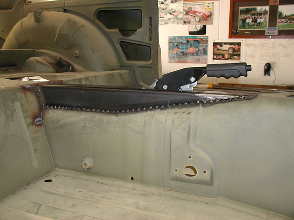